Continue to Site

Eng-Tips is the largest engineering community on the Internet

Intelligent Work Forums for Engineering Professionals

  • Congratulations waross on being selected by the Eng-Tips community for having the most helpful posts in the forums last week. Way to Go!

Weld Sizing - Blodgett vs. FEA 2

m_ridzon

Mechanical
Sep 18, 2020
101
Folks, my project is actually a mechanical engineering project, but I think my question might be suited for this structural forum instead. I've not done much weld sizing in my career, but am now deep into Blodgett's Design of Weldments for an overhead crane I'm working on. It has various fillet welds around its frame. Blodgett's method presents the weld as a line with an allowable force/length. I have two main questions to start:

  1. I was told that the allowable force/length is equal to 0.707*allowable stress. See an example in the image below. It's unclear to me the rationale that is applied to say the allowable force/length is merely 0.707*allowable stress.
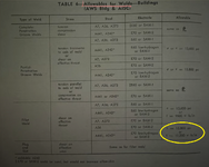
    Blodgetts_Table of Allowables.png

  2. I'm doing most of the work in FEA with shell bodies since the weldment is too complicated to do by hand. I have lots of FEA experience. The customer has requested that we prove our FEA weld sizing method by comparing an example model to hand calcs. I have run a couple of the textbook weld examples found in Blodgett's and other machine design books. My FEA weld stress is not coming close to that of the hand calcs. Below is one example from Blodgetts that I ran in FEA. His allowable force is 9600 lb/in, which correlates to 13600psi (9600 / 0.707). My FEA weld leg is 0.368" but the stress is roughly 70000psi in the root. I was expecting FEA stress near 13600psi. Can anyone share some feedback on this? I don't know how to correlate the FEA to hand calcs. I'm also open to tips on how welds are typically modeled and sized when FEA is used.
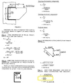
    Blodgetts_Example Problem.png
 
Replies continue below

Recommended for you

The force per length method basically determines the force required to resist an applied moment given that the force of resistance is along the line of the weld. For a simple case of a single vertical weld the Sw = d^2/6 as derived per the attached considering the weld as a line and calculating the force per inch required to resist the moment. I have always used the weld treated as a line method for designing pipe supports and attachments.
 

Attachments

  • IMG_2218.JPG
    IMG_2218.JPG
    1.4 MB · Views: 9
You could read up on how programs like Idea Statica handle weld design using FEM to get an idea of what challenges you are facing.
 
Why one would mesh a weld for a connection like this is beyond me. We did short, understandable and easy calculations for this (see Blodgett) in college.

FEA isn't best used for everything.

Agreed.

FEA can be a great tool for checking welds. But you REALLY, REALLY need to know what you are doing. I did a course on this which was quite interesting. IdeaStatica also uses FEA for weld checks, but the critical item of note is that Ideastatica uses plastic analysis and STRAIN as a failure measure not STRESS.

While we are always taught that materials fail when they reach a critical stress, it would be more accurate to argue that they fail when they reach a CRITCAL STRAIN. (Of course these are usually directly correlated and there are many complicating factors to this discussion.)
 
@ m_ridzon
Are you capable of managing this project? It is a CRANE
Do you have experience in welding, inspection and workshop testing?
 
I cringe a bit to see this question asked in the context of crane welding.
I had a feeling my post would elicit at least one response like this. It's not very productive in terms of the actual question(s) I posed at the beginning.

Why one would mesh a weld for a connection like this is beyond me. We did short, understandable and easy calculations for this (see Blodgett) in college.

FEA isn't best used for everything.

yeah, often using FEA is like using a pile driver to pound a nail.

and when you use it you have to be careful about what you are doing. FEM can give wildly different answers.

Folks, I sense the cynicism and it's not very productive. I mentioned earlier in the thread that FEA needs to be used because of the complexity of the actual geometry (the geometry images I shared herein are not the actual model, rather just a small simple test model to prove to myself how the process works; i.e., start simple). Doing hand calcs to find the forces in all of the welds would take an exceptionally long time to do; maybe weeks or months, considering all of the load cases for the work scope. It would be very inefficient. Therefore, a numerical software is being used to help determine those loads in the welds. If that means I need to extract the weld loads (instead of the weld stresses like I initially came to the discussion with), then perhaps that's the more sensible approach. But I came here seeking guidance on how my method may be wrong and what would be a better approach. And I'm getting feedback that is along the lines, "you're in left field; I don't even know why you're doing this..." Why can't we be more uplifting to our brothers/sisters in the engineering community and share some productive feedback? You folks are obviously veterans and know what you're doing. Some knowledge transfer would be nice!

Hence why the customer was asking for hand calcs.
Yes exactly. They want to see proof, rightfully so. And I want to prove to myself that it works as well. I don't like blinding relying on FEA.

For a weld in shear across the throat:

S = F/A = (F/L)(L)/((.707w)(L))

Where S is stress
F is total force
F/L is force per length of weld
L is length
w is weld leg size
0.707 is throat size for equal leg weld

Solve for w in terms of allowable stress Sa

w = (F/L)/(.707Sa) where .707Sa is allowable force per unit length
Thank you Snickster. This was very helpful and shined some light on my understanding.

@ m_ridzon
Are you capable of managing this project? It is a CRANE
Do you have experience in welding, inspection and workshop testing?
I'm not managing the project. The buck doesn't stop with me. I'm just the primary FEA user and rather than blinding running FEA to spit out results that I'm unsure of, I decided to educate myself on how weld design takes place. Hence my post here.
 
I think you're getting quality advice here. I think we're all saying the same thing anyway in that none of us like "blindly relying on FEA" (or any software for that matter).

I think it's good that you're creating a test model and comparing it against hand calcs. as a way to calibrate the FEA. That's the right way to approach this. I do wonder, though, if the real model is so complicated that you can't possibly manually check anything, how will you know if there's an error in that model?
 
I do wonder, though, if the real model is so complicated that you can't possibly manually check anything, how will you know if there's an error in that model?
Yes, that's a great point and the thought has already crossed our team's mind. We are closely collaborating with the customer (they are more experienced with crane design), and our hope is that we can all reach a consensus together, where we all feel comfortable that the FEA is producing results we can rely on.
 
I've never seen an overhead crane with geometry so complex it couldn't be solved with traditional "hand" calculations. Multiple load cases are easily dealt with in excel/mcad/smath.
 
Blodgett is using AISC's 1963 Specification which had allowable stresses of 13,600 psi for E60 and 15,800 for E70. The 1969 Specification increased the allowable stresses to 18,000 psi for E60 and 21,000 psi for E70. These match the allowable stresses still used today.

E60 Allowable Stress = 0.6*Fexx/Ω = 0.6*(60,000 psi)/2 = 18,000 psi
E70 Allowable Stress = 0.6*Fexx/Ω = 0.6*(70,000 psi)/2 = 21,000 psi
 
Why not just extract the total weld force along a weld line from the FEA and use that to design the weld if the geometry is so complicated that you can't do it by hand?

If you really desperate to actually do a stress analysis, then in the same vein of human909's suggestion, look at how IdeaStatica does it - but I would say take it a step further and just get a monthly or 3-month subscription as it probably would be cheaper than spending the time to reverse engineer how IdeaStatica does it to replicate it in Ansys.

But note even something like IdeaStatica doesn't do a pure stress analysis - it extracts the forces to perform the calculations based on applicable standards (AISC 360 or EN 1993), but it adds a plastic strain check (I think limiting it to 5%).
 
eng-2-10-25.JPG
Was the suggestion to seek out a crane manufacturer's standard also not productive? Too much of a distraction from your chosen tasks?

aws.JPGaws.JPG
 
In weldment design, is it common to screen out welds on the basis that they are not loaded heavily and do not need an explicit sizing evaluation? In other words, if the weldment has hundreds of welds, large and small, is there a method to screen out some of them to reduce the amount of weld sizing evaluations? If so, what screening approach is often used?
 

Part and Inventory Search

Sponsor