LS_SMS
Mechanical
- Sep 18, 2020
- 106
Folks, my project is actually a mechanical engineering project, but I think my question might be suited for this structural forum instead. I've not done much weld sizing in my career, but am now deep into Blodgett's Design of Weldments for an overhead crane I'm working on. It has various fillet welds around its frame. Blodgett's method presents the weld as a line with an allowable force/length. I have two main questions to start:
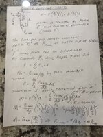
- I was told that the allowable force/length is equal to 0.707*allowable stress. See an example in the image below. It's unclear to me the rationale that is applied to say the allowable force/length is merely 0.707*allowable stress.

- I'm doing most of the work in FEA with shell bodies since the weldment is too complicated to do by hand. I have lots of FEA experience. The customer has requested that we prove our FEA weld sizing method by comparing an example model to hand calcs. I have run a couple of the textbook weld examples found in Blodgett's and other machine design books. My FEA weld stress is not coming close to that of the hand calcs. Below is one example from Blodgetts that I ran in FEA. His allowable force is 9600 lb/in, which correlates to 13600psi (9600 / 0.707). My FEA weld leg is 0.368" but the stress is roughly 70000psi in the root. I was expecting FEA stress near 13600psi. Can anyone share some feedback on this? I don't know how to correlate the FEA to hand calcs. I'm also open to tips on how welds are typically modeled and sized when FEA is used.