StressGuy
Mechanical
- Apr 4, 2002
- 481
I've had a rather strange issue come up and I'd like to see how it compare with everyone else's experience. I'm sure most of us here are aware of API 686 for "machinery installation" and the requirements for piping design. Specifically the 5D of straight run requirement.
Chapter 6, Section 3 has notes for specific piping requirements for different types of machinery. 3.1.2.6 specifically calls out the 5D requirement for pump suction piping...or so I've always been told.
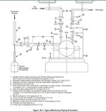
I have an issue now with a top suction pump where the piping designer has laid out the piping with the elbow directly on the pump nozzle. When I challenged him, he said that the rotating equipment engineer told him that this note doesn't apply for top suction and pointed me to figure B.3 in chapter 6. I've attached a snapsht here.
His assessment is that note 9 regarding the straight run requirement is only showing on the horizontal suction version and not the vertical suction. And, looking at the figure, that is indeed the case. The other notes like 1 and 2 and 4 are explicitly called out on both the horizontal and vertical schematics, but 9 is not.
The text of section 3 is only labeled as "suction piping" and doesn't not mention horizontal/vertical, so I've always been directed that it applied to vertical suction lines as well as horizontal.
What are you guys seeing in your designs? Have I been mislead and overcomplicating top suction layouts my whole career? It would make life a lot simpler for sure.
As a further complication, this B.3 figure says it is for "Typical Machinery" indicates pumps/compressors/blowers. Notes 9 and 13 are the only ones that appear to be pump specific. Point 3.2.4.1 calls for straight run on suction of centrifugal blowers and compressors. It also makes no distinction for vertical and horizontal and that point is not referenced on the B.3 figure at all. We've always done 5D minimum (some compressor vendors have required more) for compressor suctions whether they are horizontal or vertical.
It seems weird that that straight run would be required for all compressors, but only horizontal suction pumps.
Chapter 6, Section 3 has notes for specific piping requirements for different types of machinery. 3.1.2.6 specifically calls out the 5D requirement for pump suction piping...or so I've always been told.
I have an issue now with a top suction pump where the piping designer has laid out the piping with the elbow directly on the pump nozzle. When I challenged him, he said that the rotating equipment engineer told him that this note doesn't apply for top suction and pointed me to figure B.3 in chapter 6. I've attached a snapsht here.

His assessment is that note 9 regarding the straight run requirement is only showing on the horizontal suction version and not the vertical suction. And, looking at the figure, that is indeed the case. The other notes like 1 and 2 and 4 are explicitly called out on both the horizontal and vertical schematics, but 9 is not.
The text of section 3 is only labeled as "suction piping" and doesn't not mention horizontal/vertical, so I've always been directed that it applied to vertical suction lines as well as horizontal.
What are you guys seeing in your designs? Have I been mislead and overcomplicating top suction layouts my whole career? It would make life a lot simpler for sure.
As a further complication, this B.3 figure says it is for "Typical Machinery" indicates pumps/compressors/blowers. Notes 9 and 13 are the only ones that appear to be pump specific. Point 3.2.4.1 calls for straight run on suction of centrifugal blowers and compressors. It also makes no distinction for vertical and horizontal and that point is not referenced on the B.3 figure at all. We've always done 5D minimum (some compressor vendors have required more) for compressor suctions whether they are horizontal or vertical.
It seems weird that that straight run would be required for all compressors, but only horizontal suction pumps.


