Continue to Site

Eng-Tips is the largest engineering community on the Internet

Intelligent Work Forums for Engineering Professionals

  • Congratulations SSS148 on being selected by the Eng-Tips community for having the most helpful posts in the forums last week. Way to Go!

Steel Pile Capacity for Lateral Loads & boundary conditions

Cosmos88

Structural
Apr 14, 2025
2
For a steel driven pile, I would like to check the bending strength when subjected to lateral loads. I've seen that the pile is considered a cantilever beam and the effective length factor is taken as K=2.1 which complies with the assumption. The point of fixity is assumed to be 1 ft from ground level, and Lpile is being used to determine moments and deflections. I don't like the idea of just considering the pile to be fixed 1 ft below ground level and I was wondering if other boundary condition besides "fixed" is being used out there for steel pile capacity or if other methodology altogether is a better approach to describe the pile condition. The pile main function is to hold light weight electrical equipment.
 
Replies continue below

Recommended for you

Lpile can determine the point of no moment. 1ft below grade sounds pretty low for typical piles. If you are using Lpile why not just determine the pile moment from that program?
 
Lpile can determine the point of no moment. 1ft below grade sounds pretty low for typical piles. If you are using Lpile why not just determine the pile moment from that program?
Thank you for answering, I can get the pile moment from Lpile but what about the pile moment capacity? which restrained consideration is appropriate to determine the max bending capactiy of the pile, fixed? is the cero moment region the region where I can consider the pile fixed? Or if someone could point me out to some references explaining the design criteria.

Thanks again, I am not knowledgeable in this area.
 
The point of fixity is assumed to be 1 ft from ground level, and Lpile is being used to determine moments and deflections. I don't like the idea of just considering the pile to be fixed 1 ft below ground level
The point of fixity ( virtual fixity where max. moment would develop ) depends on the size and rigidity of pile and soil conditions . Typical should be around 5D not 1 foot below. You can perform FEM analysis assigning lateral soil springs or software Lpile ..
 
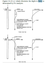
From the AASHTO bridge design spec 9th Ed.:

10.7.3.13.4—Buckling and Lateral Stability
In evaluating stability, the effective length of the pile
shall be equal to the laterally unsupported length, plus an
embedded depth to fixity.

1744809868571.png
 
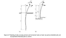
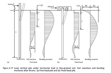
The OP looking for stability check of the pile . In my zone , depth of fixity is understood as the equivalent length of a free-standing pile with a fixed base, from which buckling check can be calculated using conventional structural design methods. The following figures from the book
Pile Design and Construction Practice ( By Tomlinson)
1744826869240.png

1744827661156.png
 
HTURKAK, the diagrams you posted match the ones from AASHTO for the depth to calculate L - 2nd time moment goes to zero for free head and the 3rd crossing point for a fixed head.

The potential discrepancy is that the text of the AASHTO spec indicates that is the effective length (K*L), rather than just L. For a fixed head pile, K would typically be take as 1.0, so still the same effective length for that case. However, for a free head, where K would typically be taken as 2.1, that would be a significant difference. I'll have to look and see if that provision is supposed to be applicable to free and fixed head piles.
 

Part and Inventory Search

Sponsor