Continue to Site

Eng-Tips is the largest engineering community on the Internet

Intelligent Work Forums for Engineering Professionals

  • Congratulations cowski on being selected by the Eng-Tips community for having the most helpful posts in the forums last week. Way to Go!

CFS Shear wall without bottom track.

canadiancastor

Structural
Apr 13, 2014
39
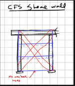
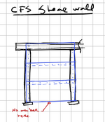
I've a got client that does CFS Metal buildings (self-storage warehouses) that wants me to double check the calculations coming out of his software. He assures me that his quoting / engineering software called MBS allows for metal sheating to be used as a shear wall without bottom track. In my wood design experience, I've always thought that axial elements are required on all 4 sides of a shear wall or diaphragm, but I'm now wondering if this is different in cold formed steel? I've had a look at "AISI - Standard for Cold-Formed Steel Framing - Lateral Design 2004" but didn't find a specific clause requiring a bottom track. Could the shear wall just be sending the shear loads into the columns? Wouldn't that require axial distribution in the sheathing?
1744828512677.png
 
Replies continue below

Recommended for you

If it is a shear wall designed via AISI tabulated values I think the limitations found in AiSi Supplement No 1. for shear walls would need to be followed. (ex. studs no greater than 24" o.c. all sheet steel edges attached to blocking or track @ required spacing.. etc.) While not specifically stated, I am under the assumption that the tables are based on typical light frame walls that would have a top and bottom track and the shear load delivered to the foundation via the bottom track attachment.

The system proposed appears closer to something like a strap bracing solution (with some extra material thrown in.) Or maybe some other "shear panel" standard other than AISI. I wonder if the design is based on a metal building design standard or testing of some sort. I would definitely be hesitant to use AISI design tables without meeting the assumptions, but there may be some other design guidance/methods that meets the system. Maybe the MBS program folks will provide some backup??

1744839265322.png
 
Without a bottom track the sheathing panels would need to be checked for axial load, and the posts would go into weak axis bending. A bottom plate is almost certaintly required (unless it is a tension only X-Brace as detailed by @RWW0002 above). The base shear doesn't just disappear.
 
I wonder if the software thinks it is attaching to a base angle (not a track) or a lower girt that attaches to columns on each side very close to the baseplate. If the bottom is not attached to anything, what reaction or restraint that connects to the earth/foundation "attracts" the distortions to that area?
 
I just got some text ouput files, and the shear wall design section looks like this:

Code:
================================================================================
 SkyCiv_4-8-25        Wall Bracing Design                       4/ 7/25  7:29am
================================================================================

 PANEL SHEAR:

                 Wall_Extents    Base  Panel     -Force(k )-  Panel_Shear(lb/ft)
   Wall  Offset  Start    End  Length  Part       Wind  Seis    Wind  Seis Limit
   ----  ------  -----  -----  ------  --------  ----- -----   ----- ----- -----
   B_SW     0.0    0.0  100.0    Open
   Long    10.0    0.0  100.0   100.0  PNRPU29    0.72  1.10     7.2  11.0 100.0
   Long    20.0    0.0  100.0   100.0  PNRPU26    0.94  1.37     9.4  13.7 100.0
   F_SW    35.0    0.0  100.0    Open
   ----  ------  -----  -----  ------  --------  ----- -----   ----- ----- -----

Needless to say there are very few details on how those calcs are done. One thing that intrigues me is the "Base length" column, which is left set to "Open" for two of these walls. The open walls don't seem to have loading or capacity, which would seem to confirm that no bottom track == no capacity.
Another possible issue for software with so little detail, is that the software is calculating with a bottom track, but the installers just aren't installing it. I'll have to see how the bill of materials or drawings are output from this software.
 
It also looks like to me, "Open" means no capacity, AND the output doesn't print 0.00, it ignores output to those fields altogether.

I am also curious about the low values of Force since the heading is "-Force(k )-" and not k/ft or ksf. Does that mean there is a total of 720 lbs of wind for one shearwall? but the walls are all 100' long giving a trib of 100/2=50'. If the walls are 8' tall, then 4' of the 8' goes to the perp shear wall to create the 720. That is less than 3.6 psf of wind. Am I reading the info wrong, I am not familiar with the output.

I've always thought that axial elements are required on all 4 sides of a shear wall or diaphragm, but I'm now wondering if this is different in cold formed steel?

I do not see any reason cold formed works differently in the force distribution portion of the analysis, since at that stage, the analysis only knows values like Area, Ix, Pounds, E, length etc. It does not utilize any material allowables and does not even consider the material. It is only during the "Allowable Stresses" portion of the analysis that material allowables and stress come into play. By then the force distribution has already occurred.
 
Last edited:
I've seen CFS systems (proprietary) that utilize hot rolled columns as the vertical elements at the ends of "shear walls", and these columns do resist the entirety of the base shear in bending. It's not really a conventional shear wall system but somewhat of a hybrid.
 

Part and Inventory Search

Sponsor