Continue to Site

Eng-Tips is the largest engineering community on the Internet

Intelligent Work Forums for Engineering Professionals

  • Congratulations SSS148 on being selected by the Eng-Tips community for having the most helpful posts in the forums last week. Way to Go!

103 year old church building - structural assessment 2

Status
Not open for further replies.

Sam165

Structural
Sep 28, 2020
12
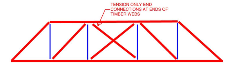
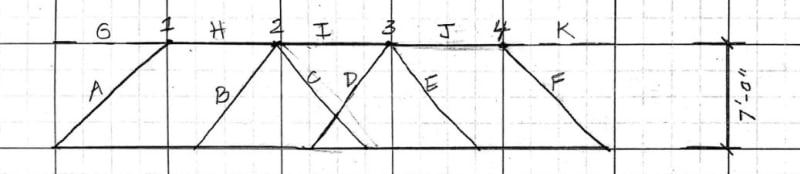
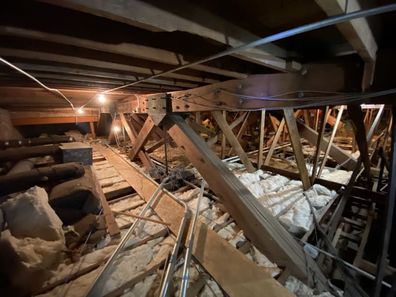
I recently finished a structural assessment on a church building that was built in 1917. The building is comprised of 55-foot long 9-ply wood trusses with 2x8 roof joists spanning 12-feet at 16-inches on-center perpendicular to the trusses. There are two specific deficiencies that I would like to pick your brain on:

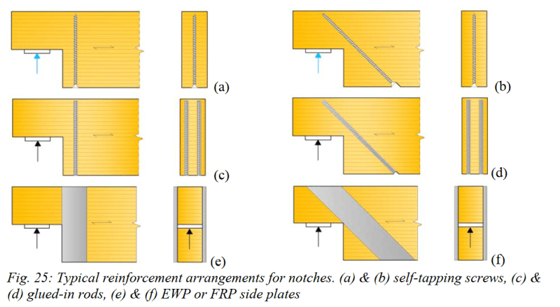
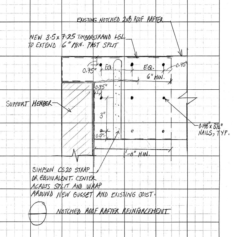
1) There are a couple of 2x8 joists at each bay that are notched at the end bearing and this has caused the member to split parallel to the wood grain (see attached pictures). I ran a calculation (see attached) to determine the shear strength of the notched member and determined that I would need two LSL members sistered on both sides of the joist to reinforce it. What is the best way to reinforce this type of notch?

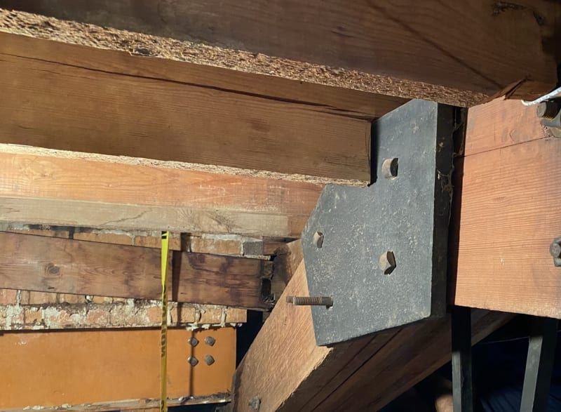
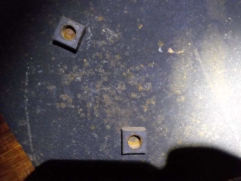
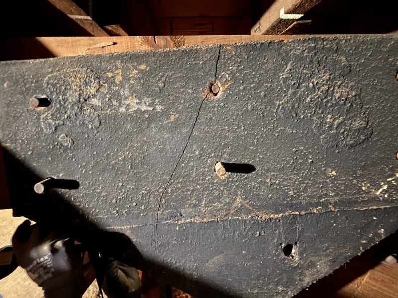
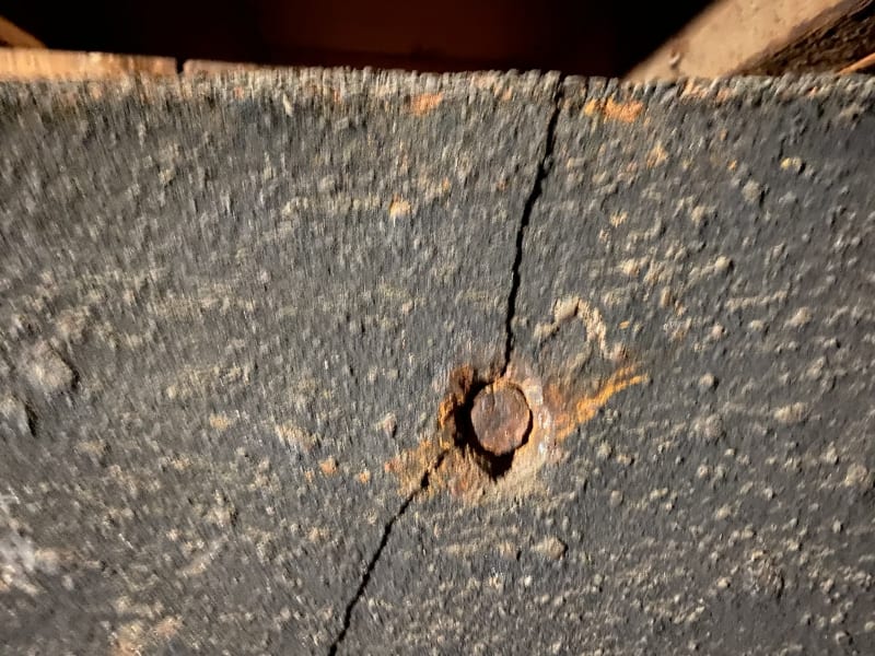
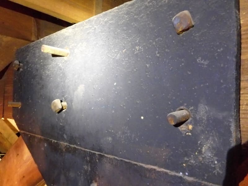
2) The truss members are attached with 1-inch thick plates (iron?) and 0.75-inch diameter through bolts. Many of the square nuts are missing and some of the bolts are too short or long to get a nut to tighten against the plate. There is one particular plate that has a hairline fracture that runs through the entire plate section. I'm thinking of reinforcing this plate with a steel plate that is placed in front of it and specifying replacement bolts for all areas that require them. I'm hoping they can get these old rusted bolts out to replace them. In addition, I was wondering if I can have them add a wood shim to the bolts that are too long so they can get the nut to tighten against that. What issues might that create?

Thanks for your help.

Sam

2x8_rafter_end_bearing_notch_a3wu4a.jpg

Overview_of_Layout_of_Trusses_and_Rafters_lorz7b.jpg

Bolts_too_short_to_tighten_nut_wtp2on.jpg

Fractured_truss_plate_gl2wqp.jpg

Close_up_fractured_truss_plate_gpsinc.jpg

Typical_truss_plate_bijmmk.jpg
 
Replies continue below

Recommended for you

When repairing notches, or when forced to notch wood members due to existing geometry (renovations), I have always used the fully-threaded screw method. I like it because:
- I believe that the APA recommends threaded screws or lags.
- There are academic papers available with methods for calculating the load in the screw. I've never seen anything similar for straps, but have seem recommendations for the use of plywood side plates. The one I've used mostly is Franke, Franke & Harte, Reinforcement of timber beams.
- The screws often end up somewhat preloaded by the impact driver. In a new member with a notch, this should prevent a crack from forming while "developing" the screw. In this retrofit application with an already cracked member, it may be possible to place construction adhesive in the crack, then draw it closed using the screws. It might close, or might not depending on how much that member has crept, etc.
- This is bound to set KootK off, but I have heard of some wood designers at the forefront of the industry considering this type of reinforcement as akin to strut-and-tie design. I believe that methodology was used for the Grade Prairie dinosaur museum connections. I haven't gone down that rabbit hole completely, but can see the efficacy of considering the wood weak in tension perp-to-grain and screws as akin to rebar.

Excerpts from the Franke, Franke & Harte paper:
Screenshot_2020-11-16_102903_hdcchy.png

Screenshot_2020-11-16_103146_ifkvgv.png
 
One thing that may make screws a bit difficult to install in this situation, I think, is how narrow the member is. Until this morning, I also didn't realize that OP's only got 2.5" of member depth left after the notch. That's not much to work with no matter the reinforcement strategy. Given that, I wonder if it might be best to just scab some stuff on to the truss to bridge the truss gusset and provide a bearing seat below the joist such that its full depth is engaged for shear.

C01_gpgioe.jpg
 
Craig_H said:
This is bound to set KootK off, but I have heard of some wood designers at the forefront of the industry considering this type of reinforcement as akin to strut-and-tie design.

Well, it sets me off if the sense that:

1) I generally support the concept. It's often how I determine what the best orientation for an inclined screw should be. The sketch below is from this recent thread with the struts added in red for this conversation.

2) It often strikes me as not entirely fleshed out yet with respect to the completeness of the load paths and the detailing. I've not yet decided if this is because the methods are in their infancy or if it's just the nature of the material. Studied in intricate detail, I feel that wood connections might actually be the most complex of all materials. Anisotropy-a-palooza.

C01_zfdrnd.jpg
 
Good point about using it to determine the ideal screw angle. I'll admit that when I watched a webinar about the Phillip Currie museum in GP, that I thought the whole concept was wild. It's growing on me.
 
@Sam165: I'm curious, is this the truss configuration that we're dealing with here?

C01_jbeman.jpg
 
Craig_H said:
I'll admit that when I watched a webinar about the Phillip Currie museum in GP...

Would you be able to provide a link to that? I'd like to check it out if it's possible to watch recorded. I'm sure it's somewhere in the StructureCraft / CWC library...
 
As for the plates I would have modern replacements cut (laser or water jet) from modern steel.
If needed you could buy modern high strength square head bolts also ( )
Those plates look cast and should all be replaced.

= = = = = = = = = = = = = = = = = = = =
P.E. Metallurgy, consulting work welcomed
 
It was part of a SEABC course with a guest lecturer. They didn't go into depth regarding the strut and tie methodology, but they implied that was how those connection nodes were designed.
 
@Craig_H: Thank you, this information is extremely helpful.

@KootK: The truss profile looks like this:

Capture_yl8vnp.jpg


@EdStainless: As much as I would love to specify new plates, that is a very expensive and laborious task which is not justified at this point in time.

Below is a rough sketch of the repair I'm working on:

Capture_u0npql.jpg
 
Status
Not open for further replies.

Part and Inventory Search

Sponsor