Eng-Tips is the largest engineering community on the Internet

Intelligent Work Forums for Engineering Professionals

  • Congratulations waross on being selected by the Tek-Tips community for having the most helpful posts in the forums last week. Way to Go!

110kW DC Motor flashover 3

Status
Not open for further replies.

CelsoSC

Electrical
Feb 7, 2021
37
0
0
PT
Hello all, please bear with me as I am a first time "poster" here.
I'm an electronic engineer and not used to service DC drives or DC Motors, I service mostly Servodrives and VFD for AC Motors.
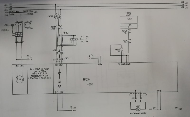
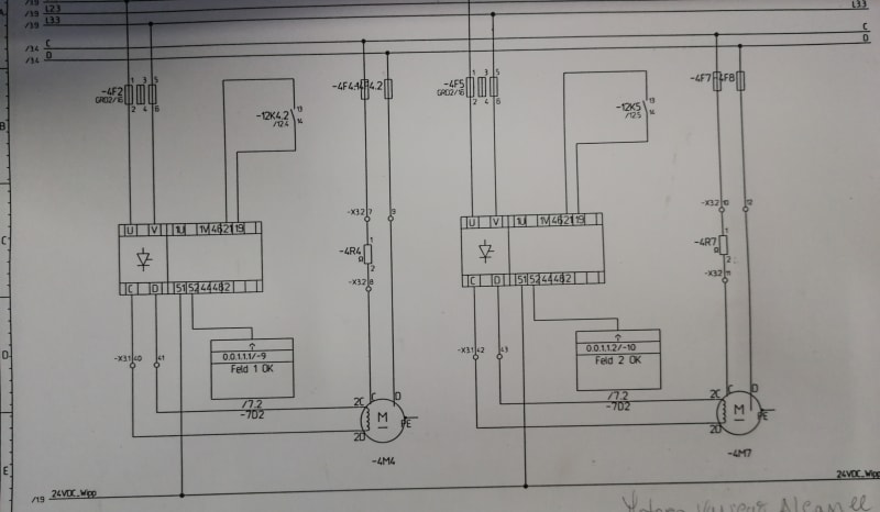
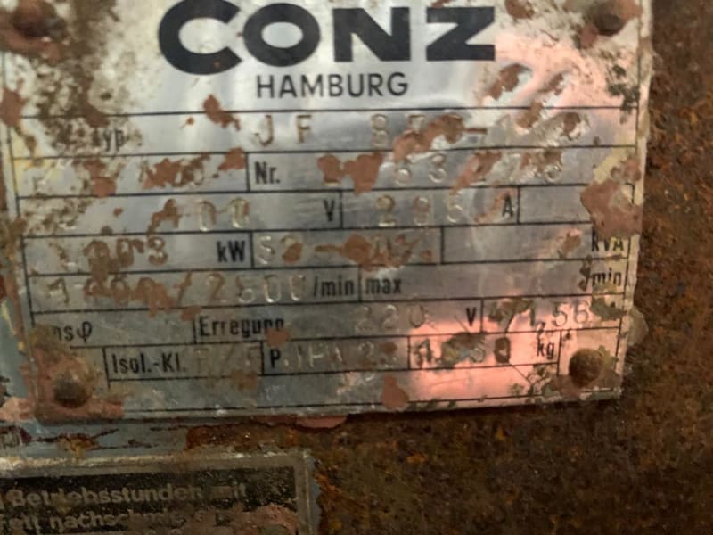
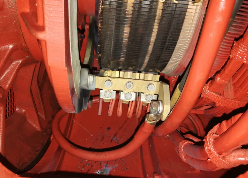
I had a job to service a SIEI Typact TDP3 SCR Drive for a system that is driving 2 german 110kw CONZ Dc Motors in parallel on a Ship-port crane.
I serviced the Drive and another Company made an overhauling on the 2 Motors.

On the first test run one of the motors had a massive flashover.
1st_testrun_ygfc9f.jpg

Testrun was made with no load on the hook and gradually increasing velocity in one direction and then in the other to about 50% of the maximum joystick position.

Motor went back to the company and returned to be tested again. On the 2nd test run the same motor did had a flashover again, but this time the pattern looked as the discharge was to the frame of the motor.
2st_testrun_001_gr3h1b.jpg
IMG_20210205_110807_ozijc5.jpg
IMG_20210205_110812_fefjs4.jpg


I asked the motor company about what could have been wrong with the motor and they told me that on the first test run the where to much humidity in the motor.
And on the 2nd time there told me that the motor was pushed to hard and went in over-speed.

I have just a basic understanding about Motors, so I can't argue with the motor company, but I may accept that on the first test run a high humidity could have let to a flashover. But telling me that I had pushed the motor to hard on the 2nd test run is not plausible, because I have 1 Drive controlling 2 motors in parallel, each motor driving 1 cable drum each, and each cable was pulled the same distance.

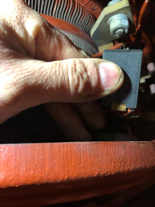
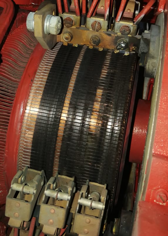
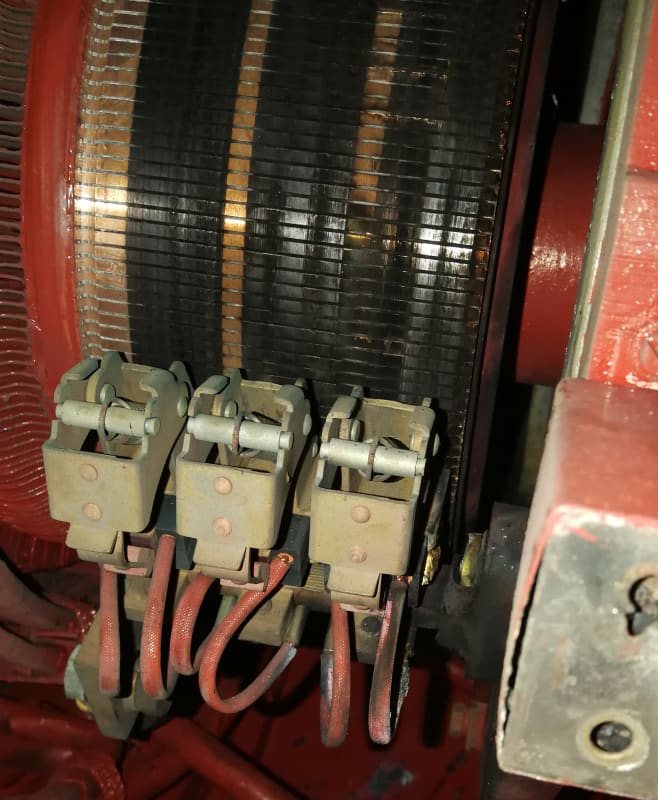
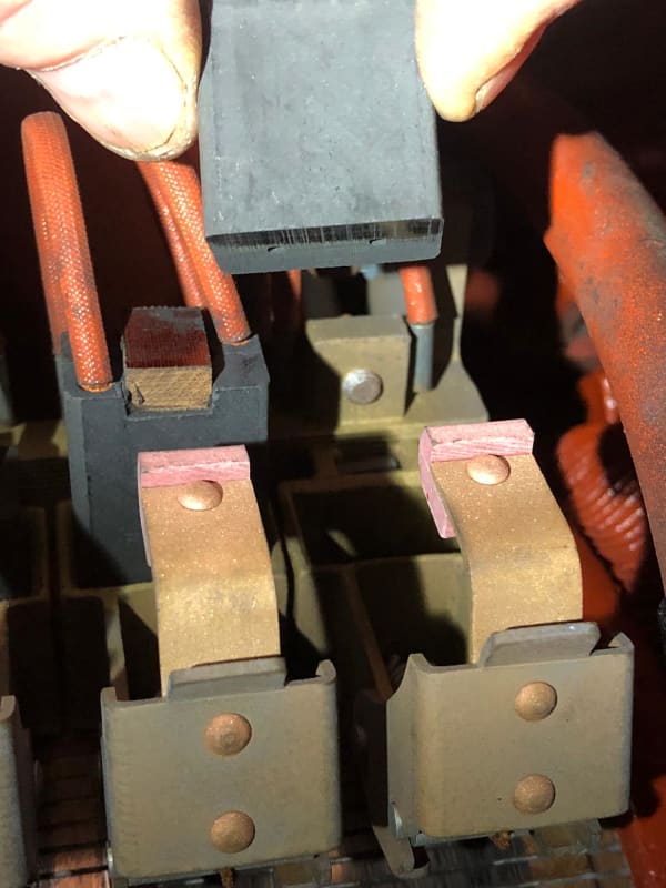
I had no change to inspect the motor on the 1st time, but on the 2nd time a had a look at the brushes and I'm quit sure that they wasn't settled in on the commutator.
IMG-20210207-WA0033_momqwv.jpg
IMG-20210207-WA0007_qsdwfv.jpg
IMG-20210207-WA0002_ep1zot.jpg

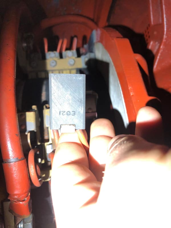
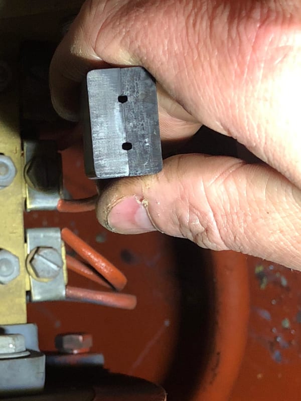
Also the pressure of one spring was very loose.

Could this had caused the flashover ?

I would like to thank for every feedback on this matter, and hope to learn more about DC Motors.

Kind regards, Celso
 
Replies continue below

Recommended for you

I suspect over-voltage/over-current due to a drive issue.
I knew that as "Ringing the Comm".
Years ago we were commissioning some large motor generator drives on hoist drums.
As part of the setup procedure, the factory tech had us install shorting jumpers across the brush-gear of the motors.
We had a two sets of four, 1300 HP motors geared together and two sets of 1050 HP motors geared together.
The tech made the same mistake several times.
It is an impressive sight when four 1050 HP or four 1300 HP generators flash over brush to brush at the same time.

In our case the drives used field forcing on the exciters.
That is an intentional short duration, 200%, over-voltage on the exciter field for fast response.
If field forcing is used, it may be staying in too long.

Another possibility is that the drive is producing high frequency, high voltage transients.

Third; A weak field for any reason may cause flash-over at relatively low loading.
issue or a weak field, either from an exciter issue a wiring issue or a faulty motor field.
Fourth; If the motors are coupled together mechanically, a relatively small speed mismatch will cause one motor to try to overdrive the other motor.


Bill
--------------------
Ohm's law
Not just a good idea;
It's the LAW!
 
First off, thanks to the OP for posting very good photographs.

Secondly, understanding the root cause failure related to a Direct Current machine is never a one size fits all.
There's a lot to study and understand. Don't expect an answer to this problem in a days readership.

Here is what I would investigate first to make sure is correct before chasing any other guesses.
The "brush entry" or connections from the field coils to the brush rack have to be known to be correct.
Until the above is determined.... everything else is moot.

Is it known whether the machine was "load tested" before it left the repair facility?

I'll check back in on this thread later.

John

 
Hello Bill,

The system is mechanically independent, but must run synchronized to be able to lower or rise the cables at the same time.
Each motor does have a independent field controller not for field forcing but for field weakening, in normal operation field is always 100%. Field weakening is only used, and must be manual set, to compensate a difference in cable length.
IMG_20201125_120937_goieqb.jpg

IMG_20201125_120930_zxfcbu.jpg


On the electrical site I have double checked everything and it seems to be OK.
But if you have any suggestion to look after or test I would highly appreciate.


Hello John,

I do not understand what you mean with "The "brush entry" or connections from the field coils to the brush rack have to be known to be correct."
Are the field coils not independent ?

The motors were not tested the first time and the 2nd time was only testes for function but without load, this was the information I have got from the technician from the repair facility.

Hello Muthu,

Is there a way to know if the brush is of the wrong grade for this motor?
The dark patina couldn't it come from the brush getting settled ?
 
Interpoles control brush sparking.
Reversed interpoles will show greatly increased sparking at the brushes as the load is increased long before a total flash-over occurs.

Are these compound motors?
Reversed compound windings will weaken the field and lead to flash-over.
Is it possible to interchange the motors or the drives.
That is a quick way to determine if this is a motor issue or a drive issue if it may be done relatively easily.

Bill
--------------------
Ohm's law
Not just a good idea;
It's the LAW!
 
"...I do not understand what you mean with 'The "brush entry" or connections from the field coils to the brush rack have to be known to be correct."
Are the field coils not independent ?

The motors were not tested the first time and the 2nd time was only testes for function but without load, this was the information I have got from the technician from the repair facility.

---------------------------------------------------------------------------------------------------------------------------------------------------------------
Celso;

Brush Entry is a term used in electrical apparatus repair, so it is understandable most outside the craft would not know its meaning.

The field pole windings, the coils of wire wound around the laminated stacked steel sheets... they have a beginning and an end lead connection.
When these lead ends accidentally get mis-connected to the brush rack (by accident) on the repair shop floor, no one knows about it until the machine is tested or placed in service.

To use waross "Bill's" words as well,
"Reversed interpoles will show greatly increased sparking at the brushes as the load is increased long before a total flash-over occurs."

If the machine is not tested before installation and its field pole windings are not connected as originally intended by the manufacturer,
the machine will not run correctly. It will make the big mess your photos clearly illustrate.

This connection mistake will not typically show up until the machine is placed in service under load.
(Stated again on purpose.)

An improperly connected Direct Current motor will run perfectly fine in many instances on a shop floor with no hint of problems.
There won't be any sparking at the brushes, there won't be any indication by reading the machine's no load current draw etc.
The machine will be given a check mark of "good to go".

Yes other causes can be investigated like brush neutral setting, the clock spacing of the brushes in relation to how they make contact
with the commutator and so on.... but the first question of "brush entry" must be answered before anything else even matters.

You should be thankful you have been given honest information from the repair technician related to the motor not being load tested.

If he indeed told you the motor was not tested, I reluctantly say that this motor must be dismantled and inspected for the connection,
and the machine must be load tested to absolutely verify it's connected properly.
And all of this won't even take place until the damage that has occurred from the present event has been corrected.

Only after verifying all of the above (said again for emphasis) one can begin to investigate other probable causes for the damage.

I wish you the very best of luck in the days ahead with this failure.

John
 
Note:
The field poles and the interpoles are two distinct differnt articles.
The interpoles are small poles between the main poles.
As the load on a motor increases, the flux pattern distorts or shifts.
When this happens the brush neutral position shifts away from under the brushes and sparking occurs.
The interpoles develop a counter flux to push the main flux back into position and maintain the brush neutral position under the brushes.
The interpoles or commutating poles are seldom shown on connection diagrams.
While the diagram will show A1 and A2 going to the armature, on of the leads will first go to the corresponding interpole and thence to the armature or brush-gear.
On the other hand a compound winding is a series winding on the main field pole.
A compound winding may be additive to develop more low speed torque.
A compound winding may be subtractive to give better speed regulation.
If a subtractive or differentially connected compound motor is stalled by a heavy load, the compound winding may overcome the shunt field winding with the result that the motor becomes a runaway series motor in reverse.

Bill
--------------------
Ohm's law
Not just a good idea;
It's the LAW!
 
A patina that dark in such a short time is anomaly. Check the OEM brush grade and replace with the same grade. I think the present grade has too much carbon content.

There service shop should have tested the interpole polarity before sending it out to the field. It will be difficult now in the field to check or correct it.

Muthu
 
Appreciate the technical clarifications Bill.

Interpoles verses field poles... they do mean something different.

Writing in a hurry, I could have said Field Frame Windings which would cover everything fastened to the works.

Somewhere in the depths of this forum I recall having to explain the difference between
a rotor, a wound rotor, an armature, and a squirrel cage rotor.

Someone kept insisting they were all "rotors". I gave up and moved along.

Also agree with as edison123 notes: "It will be difficult now in the field to check or correct it."

In the instance of this particular thread, one could insist all that needs to be done is stick one's hands into the apparatus with a wrench,
swap leads that look suspect and try the motor until it works correctly. This could be accomplished, but it would not be a very good
representation of workman like manner. Nor would it remove all the carbon from the various surfaces of the machine that now provide
multiple paths for potential to trek... including to ground. The machine would be tripping off not because it was connected wrong... but
because the thing is grounded with the assistance of carbon dust.

In studying the very good photographs again.... it's likely an optical illusion... but the commutator looks somewhat out-of-round.
I doubt it is, but the dust groove sets an appearance to me it is. I'm not saying it is... it just looks like it could be.

And it kind of appears as the mica could have been undercut a little more than what is represented.

And to nitpick a little more I would have at least wire brushed the rusty cap screws or replaced them.

It's not a perfect world though and a machine is down.

Again, good luck man.

John
 
Thank you Bill, John and Muthu for all the input and high value information.

Hello Bill,

I don't know if this are compound motors, I have to ask. On the Motors nameplate I can't read a lot.
IMG-20200721-WA0012_ea0n6e.jpg


Hello John,

Thank you for the detailed explanation,I must confess that I'm an ignorant about DC motors. On most schematics the inter-pole windings are not shown and on schematics that was showing the windings I thought that it was some suppression coil near the brushes like on some drilling machines motors.

About the commutator looking somewhat out-of-round, I tried to look on other photos but there are no better photos. But I found one photo about a brush having the surface "tilted" but has nothing to do with being out-of-round.
IMG-20210207-WA0024_dvc7p9.jpg


Hello Muthu,

I will ask if there is a part list about the motor mention what kind of brushes this DC motor uses.
 
Do you have a connection diagram?
A compound field will be shown on the connection diagram.
The simple shunt motors are much more common.


Bill
--------------------
Ohm's law
Not just a good idea;
It's the LAW!
 
Hello Bill,

I uploaded the electrical diagram in the previous post. Connection diagram of the motor on the motor plate, like on some induction motors, I can't find.
 
Celco,
better electro shops must have equipment for testing DC motors under load .This should definitely be your request in future repairs . It seems that the polarity of the main and auxiliary poles is not good and this has been explained several times how with reduced AC voltage on brusches is relatively easy to check on assembled DC motor .It seems to me that additionally edges of the bars are not well machined and allow a voltage jump from bar to bar at end of commutator.
Good luck
 
Some useful information on DC Motors can be found here, along with the two pictures following.

The first picture shows how interpoles are connected to the armature circuit, This is the arrangement I would expect with a DC crane hoist, having a solid state or Ward Lenard type speed control.
Screenshot_from_2021-02-09_19-16-50_z1dcei.png


This is a two pole compound motor. This arrangement provides very good speed regulation, making this arrangement less useful for crane hoisting applications.
Screenshot_from_2021-02-09_19-15-09_kumasu.png


As you can see in both motor types there are many connections, all of which must be correct.

Fred
 
Bill

The wiring diagram by OP doesn't show a compound wound motor.

Celco

One method to check interpole polarity. Apply 20 V AC to two adjacent brush holders and measure the output voltage between leads A1 and A2. The measured A1-A2 voltage should be less than 20 V.

Muthu
 
Fred, That diagram seems to show the series winding wound in the same direction as the shunt winding.
That is a common connection for a compound generator.
Under load, the series winding increases the field strength and causes a voltage rise to compensate for voltage drop on long feeders.
For speed regulation the series field is differentialy connected to oppose the shunt field and increase the speed by field weakening.
If that connection is used on a motor it will boost the torque under heavy loads, but the speed regulation will be poorer.

Bill
--------------------
Ohm's law
Not just a good idea;
It's the LAW!
 
Bill most of my experience with cranes was from the mechanical side of cranes having / DC NEMA resistor control, it is simple and robust, but rare for new work due to the component cost.

Lots of these (not particularly relevant to this troubleshooting exercise)
Screenshot_from_2021-02-10_18-04-56_cd173x.png


Of course The diagrams in my previous post are for the simple case of motor across the line, I put them here to possibly aid the lack of detail in the wiring diagram provided by the OP. I perhaps did not pay enough attention to the coil winding artwork.

Regards
Fred
 
Status
Not open for further replies.
Back
Top