Continue to Site

Eng-Tips is the largest engineering community on the Internet

Intelligent Work Forums for Engineering Professionals

  • Congratulations waross on being selected by the Eng-Tips community for having the most helpful posts in the forums last week. Way to Go!

110kW DC Motor flashover 3

Status
Not open for further replies.

CelsoSC

Electrical
Feb 7, 2021
37
Hello all, please bear with me as I am a first time "poster" here.
I'm an electronic engineer and not used to service DC drives or DC Motors, I service mostly Servodrives and VFD for AC Motors.
I had a job to service a SIEI Typact TDP3 SCR Drive for a system that is driving 2 german 110kw CONZ Dc Motors in parallel on a Ship-port crane.
I serviced the Drive and another Company made an overhauling on the 2 Motors.

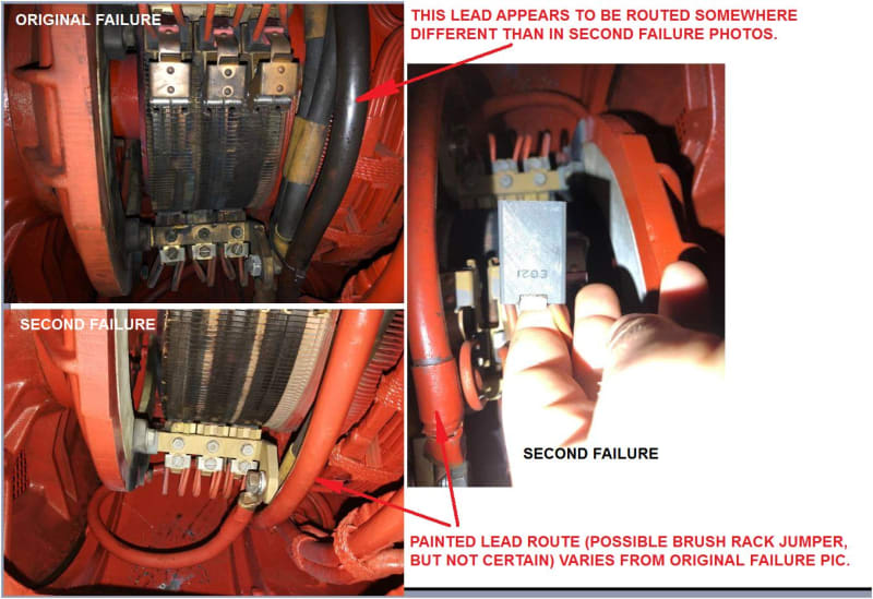
On the first test run one of the motors had a massive flashover.
1st_testrun_ygfc9f.jpg

Testrun was made with no load on the hook and gradually increasing velocity in one direction and then in the other to about 50% of the maximum joystick position.

Motor went back to the company and returned to be tested again. On the 2nd test run the same motor did had a flashover again, but this time the pattern looked as the discharge was to the frame of the motor.
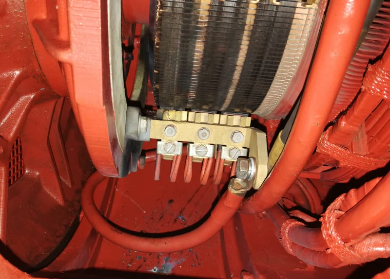
2st_testrun_001_gr3h1b.jpg
IMG_20210205_110807_ozijc5.jpg
IMG_20210205_110812_fefjs4.jpg


I asked the motor company about what could have been wrong with the motor and they told me that on the first test run the where to much humidity in the motor.
And on the 2nd time there told me that the motor was pushed to hard and went in over-speed.

I have just a basic understanding about Motors, so I can't argue with the motor company, but I may accept that on the first test run a high humidity could have let to a flashover. But telling me that I had pushed the motor to hard on the 2nd test run is not plausible, because I have 1 Drive controlling 2 motors in parallel, each motor driving 1 cable drum each, and each cable was pulled the same distance.

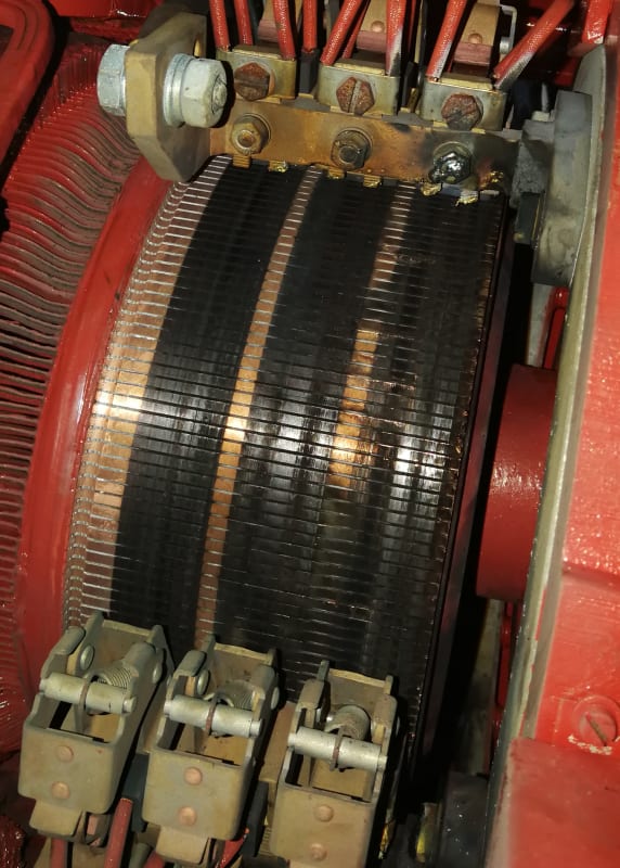
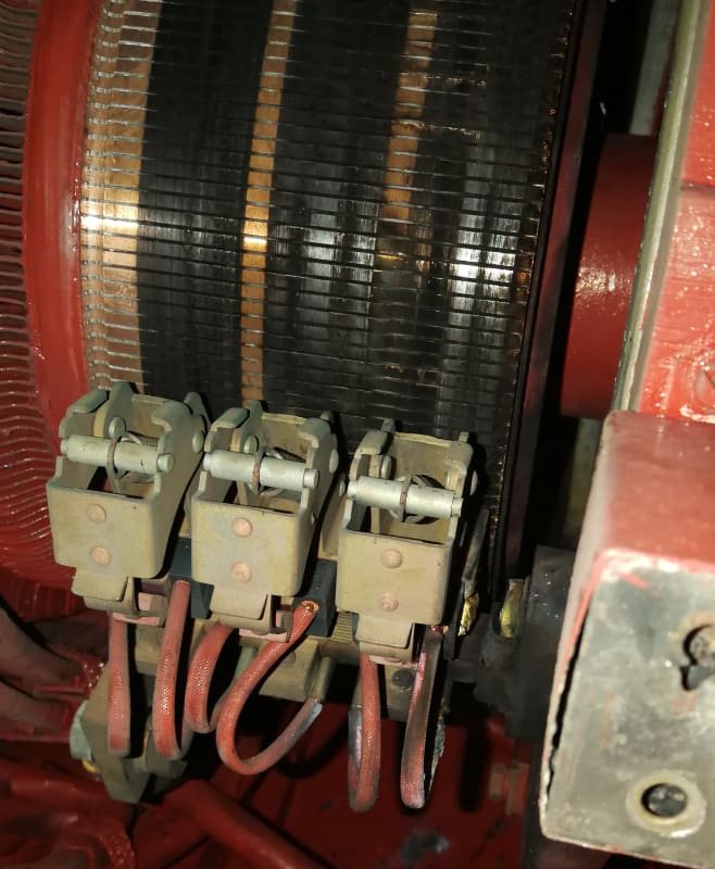
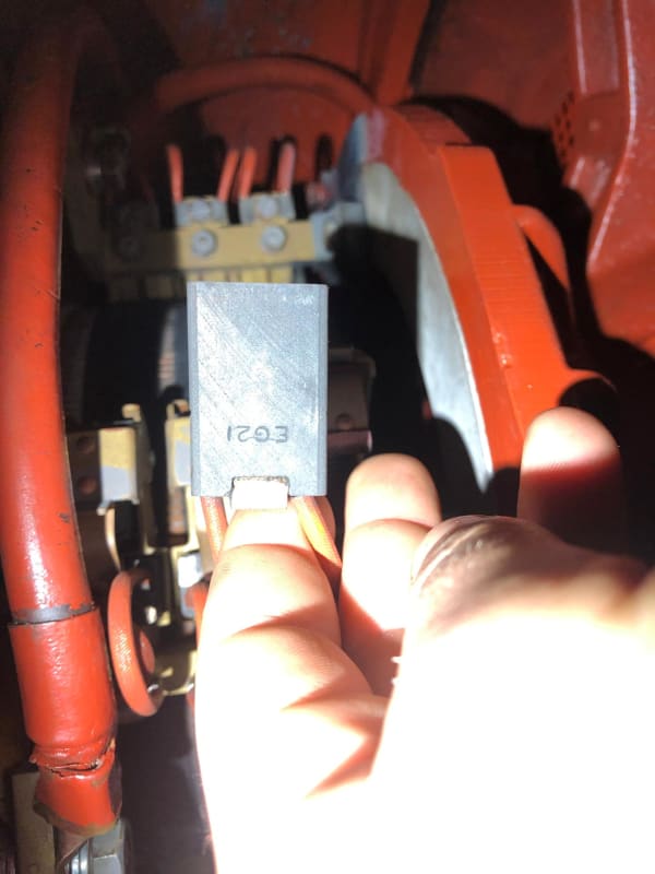
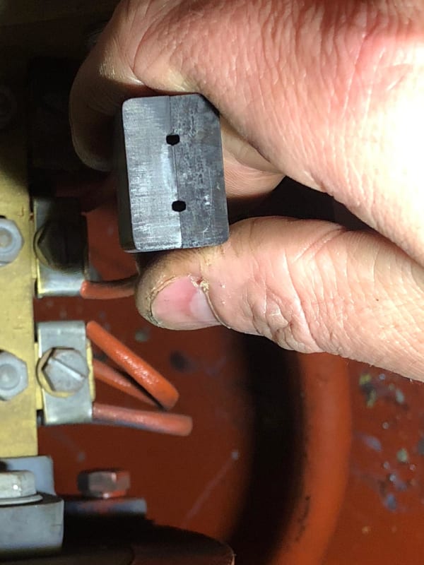
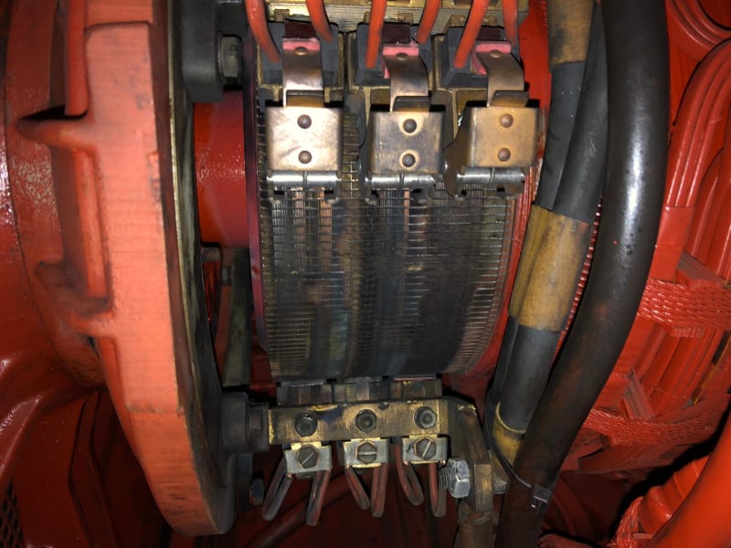
I had no change to inspect the motor on the 1st time, but on the 2nd time a had a look at the brushes and I'm quit sure that they wasn't settled in on the commutator.
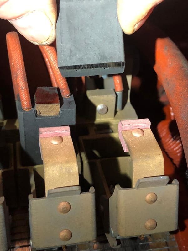
IMG-20210207-WA0033_momqwv.jpg
IMG-20210207-WA0007_qsdwfv.jpg
IMG-20210207-WA0002_ep1zot.jpg

Also the pressure of one spring was very loose.

Could this had caused the flashover ?

I would like to thank for every feedback on this matter, and hope to learn more about DC Motors.

Kind regards, Celso
 
Replies continue below

Recommended for you

Hi Fred.
My crane work was with single speed motors, two speed motors and wound rotor motors.
My DC work was in sawmills with Motor generator sets and "Amplidyne" control.
By the way, large DC motors are seldom started DOL.
The locked rotor current of a large DC motor would make the locked rotor current of an induction motor look like a non event.
The starting voltage is ramped up as the motor accelerates to limit the starting surge.
This may be done with an electronic drive.
Some version of a Ward Leonard Drive or, for smaller motors, with series resistors.
This is where a cumulative compound series winding may be used.
A differentially connected series winding will improve speed regulation by field weakening.
A cumulatively connected series winding will aid starting torque an reduce starting current by field strengthening.
These are no longer the issue that they once were as most DC motors are started and controlled by solid state drives of Ward Leonard systems with Amplidynes.
Starting torque and speed regulation may now be provided by the drives and compound motors have all but disappeared.
Now DC drives are all but gone, replaced by induction motors and VFDs.
Nostalgia warning:
When a DC motor was started on a bus or full voltage DC supply the operator stepped the motor up trough the starting steps manually.
Series resistors were used in the armature circuit to limit the current and where cut out in steps.
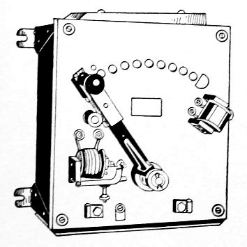
A manual DC motor starter may look like this:
image_dueeiy.png

I was instructing in a technical school and had some free time.
The head instructor asked for some help unpacking some new equipment that had just been delivered.
We wrestled a big box up onto the bench and removed the cardboard packing.
In side was a brand new, automatic, across the line DC motor starter.
Timers and contactors to cut out the resistor steps.
"What do you think of it, Bill?"
"It looks like a well built, quality piece of equipment, but Pete, does anyone use these anymore?"
"Yes, you're right Bill, it is obsolete.
In our defense, it was not obsolete when we ordered it.
The order apparently got lost for some years.
About six months ago we were asked by the purchasing department if we still wanted it.
Well, if we didn't take it we would get nothing so we said yes."
That was about 45 years ago.
That gives you some idea as to how long ago across the line DC motor starters went obsolete.


Bill
--------------------
Ohm's law
Not just a good idea;
It's the LAW!
 
Well they may be "obsolete" but "obsolete" does not get old equipment replaced. Several cranes installed in the 1890's are still in service with the original controls. Makes getting replacement parts interesting. Making open frame crane controls OSHA compliant was a problem for a while.
 
That sounds like a challenging place to work.
I love a challenge.
Are your motors running off of a common source or is there a Ward Leonard type drive for each motor?

I had a tour of the control room of this old bridge before it was replaced.
The swing and wedge motors were started and reversed by open knife switches.
It was impressive but scary.


Bill
--------------------
Ohm's law
Not just a good idea;
It's the LAW!
 
The last Ward Leonard drive to go was part of a 15 foot planer in the maintenance shop.
The last Ward Leonard crane hoist drive in crane service was replaced with a solid state drive in about 1995.
The Rotary Converters were scrapped and replaced with rectifiers in about 1977, after one lost it's AC feed, and the DC feed did not trip. The report was it spun fast enough to lift the windings out of the commutator. Bits of the DC feeder system are still in service but the users are gradually going away as equipment is replaced.
Yes it is an interesting place to work, but we are not supposed to advertise here so [wink].

Regarding the OP's system once he gets the motor working, that looks painful. If there is no closed loop feedback, and no mechanical linkage, there must be something else to true up position at least every few cycles, or the two hoist drums will drift out of position.

Fred
 
Hello Fred,

I will try to get photos of the system. The motors are mechanically independent each with it's own cable drum, but pulling the same wire.
One motor has an encoder that's connected to the SIEI Typact TPD3 Drive for feedback. To correct the speed a small adjust on one of the independent field controller has to be done. But in general the 2 motors where running syncron.


Hello John,

Now I know why you where wishing me luck. It has been a nightmare, but hopefully motor will come back next week.


Celso
 
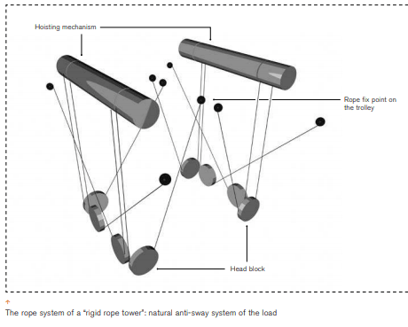
I purchased one crane with the anti sway rig similar to container cranes. All 8 ropes landed on the same hoist drum. Similar to this rigging Kocks uses on their terminal server cranes, except all of the rope is on one drum.
Screenshot_from_2021-02-18_17-54-29_sgmkfi.png


With two drums and no mechanical linkage I would prefer two encoders, one is reference hoist drum current position, the other is on the hoist drum that is speed trimmed, connect the two encoders to a compere, and use the output error signal to trim the speed on one of the two motors.
I did not see anything like that in the wiring diagram. But I did not see the encoder you now report in the wiring diagram either.
 
Hello Fred,

You are correct, on the diagram is a tacho signal as feedback, but this was changed right in the beginning to an 1200imp/rev encoder together with an overspeed sensor.
I'm not very familiar with cranes in general, I'm more used to sit on my desk and repair electronic devices.


But I must confess that is fascinating to see some bunch of electronic components driving some massive machines.
And so far, in this matter I had big luck. The where no information about SIEI Typact TDP3 SCR Drive. Mr. Mustapha Abulhuda, a person I found on E-bay selling some SIEI spareparts, gave me all documentations he had about the drive and I own him a big thank you. And also here, as my first post and getting advice on what could be wrong with the motor, I have to thank you all folks.

Celso
 
Celso;

Nightmares turn into redeeming experiences you will always remember for the education they gave you.

Once upon a time, Eddy Current drives differentiated the men from the boys.

Today, Direct Current motors are somewhat following the same curve.
One day they will be a "thing" of the past.

Thank you for keeping the curious crowd ... updated.

John
 
Hopefully you are past needing this now. SIEI seems to be a subsidiary of GEFRAN it was hiding. Some DC drive products are offered on their website.

I think this is the page with the current generation of the drive you are working on. The model numbers hint at family resemblance.

I have been through the unhappy experience of working with early generation DG hoist driver after they became technologically obsolete. GE once offered to provide some really detailed information on a hoist drive so we (the customer) could engineer a replacement for a unavailable hall effect current sensor. I declined the offer, and we eventually replaced all of the drives on that crane.

Planning for component obsolescence is unfortunately just one more thing owners need to do - and often do not until something breaks that can't be repaired at a reasonable cost.

Regards
Fred
 
Hello,

I have some updates ...

What is the probability to have a motor failed again. Extremely high, especially if you receive a motor that was not tested at all.
I have to close this case on my side, I don't want to blame no one, but some body is not doing the job well.

Thank you all for your help.

Celso
 
Been there too[thumbsup2]. Even good shops that test everything out the door occasionally send out a bad motor. Does not matter how good the shop is, its a warranty call.[morning]

Fred
 
Hello Muthu,

There still is a problem. As the motor came back from the shop to be mounted on the crane we tested it and it only took 30 seconds to develop a flashover again.
This time we swooped the position of the 2 motors to be sure that there where no mechanical problem with the gearbox or the electrical cables from Drive/fuses/resistor/exciter to the motors.

I had several meeting with the company in charge of the repair of the motor, and tried to hand over the informations that was given me on this forum.
They always denied that the connection could be wrong and as I asked for a test report with full load, they told me that this was not necessary because the have a lot of experience and it was never necessary to carry out such a test/report. So I was quite sure that the motor would fail again and it failed.

I was monitoring the current of the armature on both motors, there was a slightly difference of the current 1-2 Amps less on the "good" motor. There was just very little sparking till the current hit 90A - 100A, after that the flashover. It was very fast and I had no time to switch off the drive fast enough, and even I don't know if it is safe to disconnect a DC Motor abruptly.

The damage is an exact 1:1 copy of the photos of the second time the motor failed.

Celso


At this point you may be better to check the connections yourself.
I would first try using a hacksaw blade as a magnetic polarity probe.
Put a low voltage DC across A1 and A2.
That is the armature circuit including the interpoles.
Use a short length of hacksaw blade and a compass to probe the polarity of the armature field and the interpole field.
Compare the good motor with the bad motor.

Bill
--------------------
Ohm's law
Not just a good idea;
It's the LAW!
 
Celso

Thanks for the update. Load tests are expensive, that's why it's only a type test even for OEM's. As a rewinder, I do no-load tests only for 99% of the jobs.

As I said before, there are other ways to test the DC machine connections without doing the load test. The repair shop is either unaware of such tests or is being just pigheaded.

I am more positive that in your case, the interpole connection is wrong since the flashover is happening only on load.

Muthu
 
Celso, it was an excellent idea to swap the placement of the two motors to confirm the integrity of the electrical / mechanical installations, etc.

Acknowledging that load testing a Direct Current motor is not possible in every repair facility.

Numerous other tests can be made however on a motor before re-assembly for assurance the repair is proceeding without errors.
Voltage Drop tests on the interpoles and the field windings are very important steps in knowing the condition of the apparatus.
These tests are performed during disassembly and original inspections however. Not as an afterthought during re-assembly.
And marking, tagging the all important leads to the brush rack is extremely necessary for everything discussed so far.

Having looked at the original posted photos considerably longer than I would normally do for an Internet forum,
I keep returning to the three pictures that show a lead route going and coming from a different place.
Brush Rack jumpers are not very long typically, and are normally just long enough to make their respective connections.

2-28-B_c5nxhg.jpg


I think the motor is connected improperly. None of us reading this forum can prove the connections though, and there is always a chance
we are all wrong in our hypothesis because we are not in the motor's physical presence.

Repair history on the motor is becoming a little foggy. Another factor to remember is repair shops can make the mistake of unknowingly
following someone else's errors.

Again, I'm wishing you success in navigating your nightmare.

John
 
Hello,

John, you nailed it.
Finally good news, after some investigation, today I discovered that there is a 3rd party evolved in this process. The 1st motor overhaul was made by the company hired by my client and this company has lack of experience with DC motors.
2nd and 3rd overhaul was made by a well know company in my country, but they failed to do it right because o the first overhaul someone did change the interpole wiring.
As I only was talking with the 1st company, for sure they ignored my information about the interpoles and didn't pass the info to the 2nd company.

Today at the 2nd repair shop a load test was made and wiring was checked to be wrong. At 60A motor was sparking and after interpole wiring change motor was running fine.

In the next few days I will give some feedback of the motors in Place and hope to have some time to take some pictures.

Again, thank you all !!!
 
Waross said:
waross (Electrical)
8 Feb 21 23:01
Interpoles control brush sparking.
Reversed interpoles will show greatly increased sparking at the brushes as the load is increased long before a total flash-over occurs.
Got lost in the background noise.

Bill
--------------------
Ohm's law
Not just a good idea;
It's the LAW!
 
Hello Bill,

No I didn't lost you in the background noise. Everyone pointing me at the interpoles was right. And I "repointed" several times and no one in the repair shop was lisening.

Regards, Celso
 
I know the feeling.

Bill
--------------------
Ohm's law
Not just a good idea;
It's the LAW!
 
Status
Not open for further replies.

Part and Inventory Search

Sponsor