Eng-Tips is the largest engineering community on the Internet

Intelligent Work Forums for Engineering Professionals

110kW LV Motor Unbalance current 2

Status
Not open for further replies.

InvisibleElect

Electrical
Aug 19, 2015
1
0
0
QA
We have two identical 110kW, 199A FLC,415V LV Motors (star-delta starter)in plant for N2 compressor application. By measuring current manually in 3 phases by three calibrated clamp meters, we observed as below at low pressure (unloading)

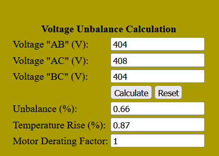
Motor A Unbalance in reading. (L1=178A,L2=194A,L3=184A at Voltage L1L2=404V,L2L3=408V,L1L3=404V) When I calculated by SQRT method, average current is found 185A by sqrt (SQ of currents/3) and Voltage unbalance is 0.5% by (Max-Average)/Average. Ratio of Current Unbalance/V unbalance is calculated as 8.9

Motor B Unbalance in reading. (L1=182A,L2=195A,L3=187A at Voltage L1L2=404V,L2L3=408V,L1L3=404V) When I calculated by SQRT method, average current is found 186A by sqrt (SQ of currents/3) and Voltage unbalance is 0.5% by (Max-Average)/Average. Ratio of Current Unbalance/V unbalance is calculated as 9.5

Motor temperature in both is normal and additional cooling fan is also provided for this enclosed unit.

As we know current unbalance can reach up to 10x voltage unbalance at full load, in our case it is less than 10. Will the 9.84 in motor B is a worry ?
 
Replies continue below

Recommended for you

You do not have to worry as long as the current is below the rated value.
Very often the currents differ due to various winding imperfections.
Different resistances of phase windings are the most common imperfection of windings, not because of different number of turns per phase, but rather because of different sizes of coils.
It would be good to have the ability to accurately measure the resistance of phase windings.

a_haazge.png
 
For motor A: (178, 194, 184 A) max current unbalance occurs on L2 and is 4.7 percent.
For motor B: (182, 195, 187 A) max current unbalance occurs in L2 and is 3.7 percent.

Both are slightly high - should be somewhere closer to a max of 3%. However, you have a random-wound coil design - which likely has some pretty good eccentricities built into it. That means it is not uncommon to run a bit higher (typically to 5%).

I take it the current readings were "instantaneous" and not "continuous trend" values. More potential for variability when looked at that way, even though you presumably measured all three phases at same time. (Example: each clamp meter has its own error tolerance, as does anything used as a data acquisition system).

Be aware that heating is going to be a function of the sqaure of the current - although the "machine" temperature may remain fairly constant with this current variability, the difference between specific phases can be more noticeable (e.g., 178 A = 0.894 pu; 194 A = 0.975 pu ... which means the lower current phase is seeing roughly 80 % of its design temperature, while the higher current phase is seeing 95% of the design temp.) Neither is above unity, though, so it's ok for now.

Converting energy to motion for more than half a century
 
Unbalanced supply voltages affect the rotor more significantly than the stator due to negative sequence flux rotating in the opposite direction leading to additional rotor currents at nearly twice the frequency. These high frequency currents will produce high eddy current and hysteresis losses, which are proportionate to the square of the frequency and the frequency respectively.

Muthu
 
Muthu - I agree, that's typically something to watch for on wound rotor motors where the rotor winding is insulated. Squirrel cage motor rotors I think are pretty robust, so I don't think unbalance during run is going to challenge the rotor itself, but maybe the rotor heat would contribute to overall heating to some extent which could challenge the stator a bit more.

I have looked at the derating curves for operation with unbalanced current. You can work out the math of how they come up with the curve (below) but the logic behind that math is a little fuzzy to me at the moment. I think I'm not sure if it's empirical or theoretical or perhaps a combination (empircal parameters plugged into theoretical model).

Screenshot_2022-05-23_094248_wjuxws.gif


That was a little bit of rambling to explore the subject in general. But to focus back on op, those derating curves based on voltage unbalance (typically current unbalance can be 5-10x more). Op has both voltage and current balance readings and there is certainly no derating indicated for his numbers.


=====================================
(2B)+(2B)' ?
 
Status
Not open for further replies.
Back
Top