Continue to Site

Eng-Tips is the largest engineering community on the Internet

Intelligent Work Forums for Engineering Professionals

  • Congratulations IDS on being selected by the Eng-Tips community for having the most helpful posts in the forums last week. Way to Go!

11kv voltage collapse during peak load at 5

Status
Not open for further replies.

newelecteng

Electrical
Apr 8, 2016
64
Hi all,

we have 6 gas engines (0.4kv,1950kw each) connected to 11kv bus throw (0.4kv/11kv 3MVA transformers). this power station feeds residential loads in the countryside (air conditioners, water pumps, lighting, and workshops) throw 20km, 175mm2 OHL .

I noticed the following during the summer period when the station breaker is closed, the loads start to rise gradually within an hour until they reach about 380 amperes in the station breaker, then a sudden jump in the current occurs, as a result of this breaker trip, especially at peak times (at noon). And when we switch on this barker again it trip within 1 hour. But during the night or dawn period, this problem does not occur and the loads are about 320 amps in this braker.

If we observe this problem from the load side at the end of the line at the branching distributing lines, we notice that the voltage is initially about 10.6 kv when the distribution lines are disconnected, then when all the lines are connected and the load begins to rise , we notice that the voltage drops gradually from 10.6 to 8 kv within an hour and then a jump occurs in the current and a severe voltage breakdown then the main station circuit breaker trip.

The peak load is about 7MW

please see the attached SLD
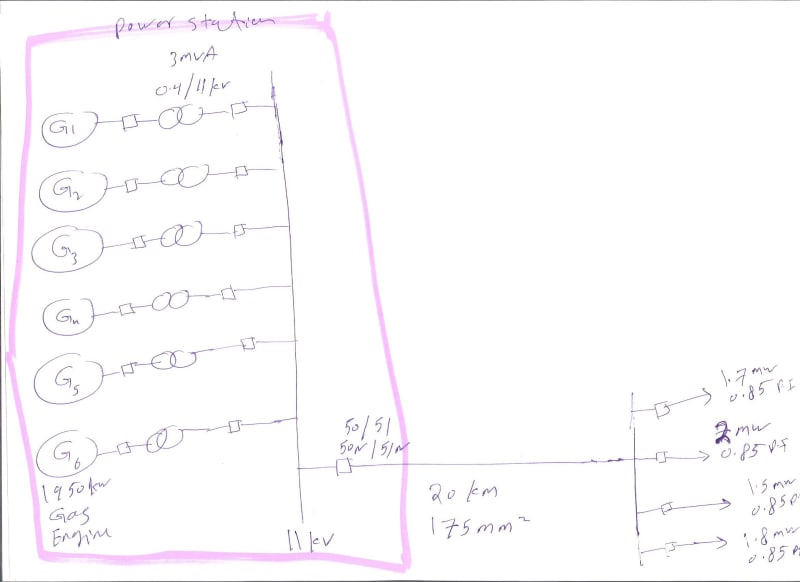
001_updt11.jpg
 
Replies continue below

Recommended for you

What do the relay event records show?

I’ll see your silver lining and raise you two black clouds. - Protection Operations
 
It happens during noon time in summer, you said. This suggests that the large air conditioning load is being added in a short time which is causing voltage dip and consequent higher draw of current by the AC equipment.
One way you can handle this is by providing Automatic power factor correction capacitors at load end to minimise VAr drawal / voltage drop. Further, if switching on of ACs can be staggered, that will be great help by reducing the starting inrush.
 
8 kV on an 11 kV line is 73%.
You may have large motors or a lot of air conditioners stalling.
As each unit stalls, the locked rotor current will drive the voltage lower resulting in a cascade effect.
Modern controls tend to restart A/Cs after a random delay. Some units may have to be restarted manually.
Have you considered installing a bank of voltage regulators to improve the downstream voltage?

Bill
--------------------
Ohm's law
Not just a good idea;
It's the LAW!
 
the relay at Power station shows spike in current and voltage drop slightly.
 
bill

the voltage is (8 kV on an 11 kV line is 73%) if we install capistor bank do you think it will help even the voltage drop is very big
 
I am amazed you only seem to be concerned about the breaker tripping and not the 27% voltage drop. The motors in customer equipment can be damaged by supplying such low voltage. In my region, we are required to have no more than a 5% drop, and customers sometimes complain about a 3-4% voltage drop.

Reactive power does not travel very far very well, so trying to ship ship several MVar a distance of 20 km on an 11 kV line results in terrible voltage drop. You may need multiple stages of capacitor bank so that the flows on the 20 km line stay somewhat close to unity power factor. Having a single very large capacitor bank could result in excessively high voltage under light load conditions.

 
Over-voltage at light loading is always a concern with bulk (un-switched) capacitor banks.

Bill
--------------------
Ohm's law
Not just a good idea;
It's the LAW!
 
Based on your SLD, the installed capacity is 18MVA @ 11kV. That means your 11kV station breaker
should be able to handle comfortably upto 1000Amps @ 11kV. If you say that it trips at 380A, then in my
opinion there is some serious error in proetction relay settings.
Also your SLD shows 20km/ 175sq.mm (is it 185sqmm or 175 sqmm?) feeder. I am assuming it
is a cable feeder. The continous current carrying capacity of a 11kV/ 1Cx175sq.mm cable is 550A only.
It looks like the cable is not sized enough for the steady state voltage drop for 18MVA.
Therefore, could you please provide,
1)The make/ model/ AS LEFT settings of 50/51 protection relay associated with the 11kV station breaker?
2)The correct size/ type of the 11kV feeder?
 
Kiribanda

its is not cable its OHL 175mmsq. and the protection working fine its within set point i already carry out secondarily injection on the relays
 
If it is 175sqmm then the conductor should be LYNX. It is having maximum ampacity of 400A.
How this can be used to trasmit 18MVA @ 11kV without a considerable voltage drop? Protection
settings has nothing to do about the steady state voltage drop.
 
A couple of corrections:
The station has six times 1950 kW sets. At 0.8 PF that is a capacity of 14.625 MVA
The load is given as 7 MW at .85 PF = 8.24 MVA
The breaker holds in at 380 Amps. The breaker trips at some value above that.


newelecteng, what is the trip set at on the breaker?
What current are you seeing at the time of tripping?

Bill
--------------------
Ohm's law
Not just a good idea;
It's the LAW!
 
hi bill

The maximum capacity of these ensigns is 8.5 MW due to derating. the maximum load during peak is around 6.9mw. the line is 20km, 175mm2 OHL, aluminum

This problem occurs when we reach maximum load at mid day or afternoon when the amps reach 370 to 380. but this proplem disappear when the amps below 350.

If we see this problem from Power station you will see big jump in amps it reach 480 amp and the barker trip on over current (the over current pickup is 450 amps).

but if you see this problem from load side at the end of the line you will notice that the voltage is initially about 10.6 kv when the distribution lines are disconnected, then when all the lines are connected and the load begins to rise , we notice that the voltage drops gradually from 10.6 to 8 kv within an hour and then a jump occurs in the current and a severe voltage breakdown then the main station circuit breaker trip.
 
If you have no local loads or if you can make some arrangement to handle overvoltages on local loads, you can try compensating for line voltage drop.
Use a CT on each generator an outgoing line and drop the current across a resistor. Tap a voltage from the resistor and use it to bias your sense inputs to the AVRs.
As the load increases, the bias will increase the generator voltages to compensate for line voltage drop.
This may help if your problem is primarily caused by low voltage.
If it is just an overloading issue you may have to shed loads.

Bill
--------------------
Ohm's law
Not just a good idea;
It's the LAW!
 
bill

the generators have max voltage output 0.42kv

is it possible for this line 175mm2,aluminum,11kv,20km to handle 6.8MW on this voltage level (what is the maximum amps)
 
Do your transformers have taps?

Bill
--------------------
Ohm's law
Not just a good idea;
It's the LAW!
 
bill

the transformers already on the max tab 12.1kv

is it possible for this line 175mm2,aluminum,11kv,20km to handle 6.8MW on this voltage level (what is the maximum amps)
 
Do know the charging current of the line? Consider installing enough capacity to balance the charging current as a first step.
You can probably double that amount of capacity without serious voltage rise issues.
Do your load end distribution transformers have taps?

Bill
--------------------
Ohm's law
Not just a good idea;
It's the LAW!
 
I dont know the harging current of the line

what you mean by "installing enough capacity to balance the charging current as a first step"

our distribution transformers is 11/0.4kv Dyn11 and its already on its min tap.
 
Status
Not open for further replies.

Part and Inventory Search

Sponsor