Continue to Site

Eng-Tips is the largest engineering community on the Internet

Intelligent Work Forums for Engineering Professionals

  • Congratulations IDS on being selected by the Eng-Tips community for having the most helpful posts in the forums last week. Way to Go!

11kv voltage collapse during peak load at 5

Status
Not open for further replies.

newelecteng

Electrical
Apr 8, 2016
64
Hi all,

we have 6 gas engines (0.4kv,1950kw each) connected to 11kv bus throw (0.4kv/11kv 3MVA transformers). this power station feeds residential loads in the countryside (air conditioners, water pumps, lighting, and workshops) throw 20km, 175mm2 OHL .

I noticed the following during the summer period when the station breaker is closed, the loads start to rise gradually within an hour until they reach about 380 amperes in the station breaker, then a sudden jump in the current occurs, as a result of this breaker trip, especially at peak times (at noon). And when we switch on this barker again it trip within 1 hour. But during the night or dawn period, this problem does not occur and the loads are about 320 amps in this braker.

If we observe this problem from the load side at the end of the line at the branching distributing lines, we notice that the voltage is initially about 10.6 kv when the distribution lines are disconnected, then when all the lines are connected and the load begins to rise , we notice that the voltage drops gradually from 10.6 to 8 kv within an hour and then a jump occurs in the current and a severe voltage breakdown then the main station circuit breaker trip.

The peak load is about 7MW

please see the attached SLD
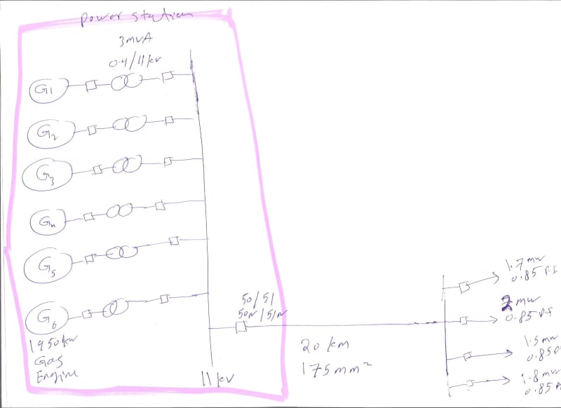
001_updt11.jpg
 
Replies continue below

Recommended for you

Note - I am not a power distribution engineer, I sit next to one.
I just realized the PF was discussed further up in the thread.
The current situation you are describing contains these factors
Loads - current draw increases dramatically as voltage drops - typical of motor loads.
Power Line - Power lines do not transfer power efficiently at low power factors.
This slideshare goes into the subject in a bit more depth.

This slide share on voltage regulation is focused on tap changers, but it has a good discussion on where to place them which also applies to capacitors.

What Bill is proposing is that a good place to start is compensating for the reactive demand you know about by adding some capacitors out in your system. A useful place to start is just compensating for the power lines reactive demand (possibly including transformer reactive demand).

Fred


You show the loads as 0.85 PF and the plant as 0.8 PF.
The difference represents the inductive reactance between the points that the two measurements were taken.
As for charging current, I misspoke.
What I meant to say was the no-load current. That is, the current needed to energize all of the transformers in the system.
One limit on the capacity of a transmission line is the ability of the On-LOad-Tap-Changers to compensate for line voltage drop.
It sounds as if your line is badly overloaded.
A long OHL will have significant inductive reactance. This will cause a voltage drop that may be mitigated by capacitors.
The magnetizing current of the transformers will add to the reactive current and the resulting line voltage drop.
A solution from long ago, when unswitched capacitor banks were used for power factor correction to avoid over voltage at light load was to connect capacitors to large loads, usually large motors or in some cases such as a lumber dry kiln, to groups of smaller motors so that the capacitors were switched by the same contactor which switched the motors.
This gave us switched capacitors without the cost or labour of adding capacitor switching.
This was seat of the pants or red neck engineering. Using a knowledge of the basics to solve a problem when neither the information nor the instruments to gather the information may have been available.
Subject always to actual conditions and judgement, we would often use 200% correction. That is, if a motor demanded 5 KVARs to correct the PF to unity we would connect 10 KVARs. This worked well for an industrial plant with a combination of a lot of smaller motors and a few large motors.
I am sure that some readers will be able to suggest examples where this solution would not be successful. That is where judgement came into play. We would look at the load profile of a plant and try to anticipate these situations and search for other solutions.
Back to your case.
As a first step in an economical improvement:
Determine the no-load or magnetizing current of each distribution transformer and from that calculate the VAR demand of the transformer.
Connect twice that amount of capacitors on the secondary, so that when a transformer is off-line the associated capacitors are also off line. This will go a long way towards avoiding over-voltages.
But this may not be enough to solve your problem.
It appears that your system is long overdue for a major upgrade.
I am not confident that we have identified the root cause of your problem.
The first rule of trouble shooting is to accurately determine the root cause of the problem. The second and third rules are: See the first rule.
We have two possible issues.
1. Is the problem motors stalling due to low voltage.
2. Is the problem too much load for the system capacity.
A solution to the first problem may be capacitor banks. A better but more expensive solution may be the installation of a bank of voltage regulators at the load end of the line.
A solution to the second issue may be load shedding or it may be measures to increase the output of the generating plant.

Bill
--------------------
Ohm's law
Not just a good idea;
It's the LAW!
 
FacEngrPE; I didn't see your post until after I had posted my reply. Thank you for the support.

Bill
--------------------
Ohm's law
Not just a good idea;
It's the LAW!
 
Bill your explanation is better than mine, we must have been typing at the same time.

Power system stability is a subject that has many contributors. Here we have a small system, which probably has limited resources and budget (a guess). As a result it is likely that a lower cost solution that provides a somewhat acceptable result is better than a more expensive technically perfect solution.

If this was my problem to solve I would want more information about where in the system the loads are. That might help answer questions about the best places to inject reactive power.
 
Waross,

If you are seeing dips in voltage of 20%+, I don't think that voltage regulators are going to save you if you are that close to slipping. The voltage problem get worse as the voltage dips because the voltage dip causes more vars to be consumed, which causes it to dip further. You can get capacitors that are only in service to provide starting var support and not have to worry about normal running overvoltage.

One possible solution if the voltage is dipping when unit is started is get a VFD or soft start to limit the voltage sag during motor inrush.


Status
Not open for further replies.

Part and Inventory Search

Sponsor