Continue to Site

Eng-Tips is the largest engineering community on the Internet

Intelligent Work Forums for Engineering Professionals

  • Congratulations KootK on being selected by the Eng-Tips community for having the most helpful posts in the forums last week. Way to Go!

18 MW synchronous motor - thyristor triggering problems 2

Status
Not open for further replies.

Skogsgurra

Electrical
Mar 31, 2003
11,815
The ubiquitous rotating exciter with thyristors shorting the excitation winding to turn it into a starting winding has been used for decades. And mostly done its thing as expected.

The trigger units, we have had problems with Siemens and ABB ones, start to show problems. They are sometimes delivered as "aftermarket" items and sometimes they have the original brand stamped on them and sometimes they have been delivered from an engineering company that seems to be a one man show.

Some of them cannot be run for more than a few minutes until they get hot and let the (almost) grey smoke out and some work only marginally. The main problem with those that work marginally is that thyristor gating pulses are extremely short. I could live with 100 microseconds, even if I think that a few hundred microseconds would feel better.

But this one has around 6 microseconds and that is a far cry from what I think is acceptable:
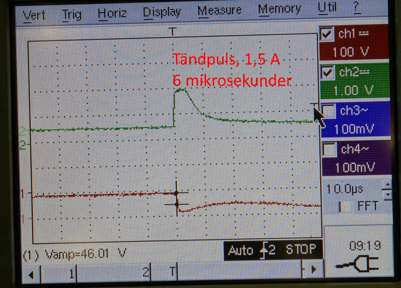
T%C3%A4ndpuls_1_wrhitr.jpg


It results in triggering happening randomly. In picture below, the first doesn't trigger at all and the two following half-waves start to conduct but the latching current isn't reached. With OK gating, the voltage across the thyristors goes to zero when the thyristors conduct.
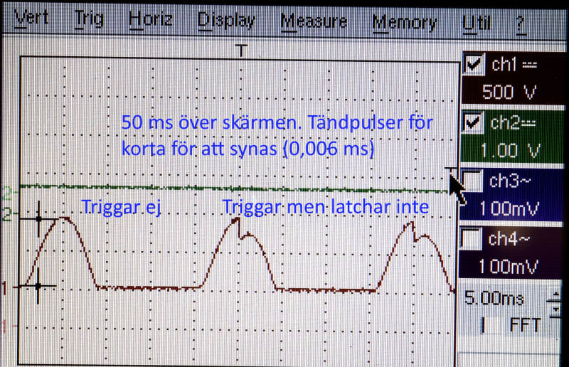
Triggar_Triggar_ej_1_gaf0yg.jpg


All technical competence seems to be lost - or very difficult to get in contact with. My questions are:
1. Anyone have this problem
2. How did you move on?
3. OR - is it really possible to run with gating pulses as short as 6 us 410 A puck thyristor?
4. Any other thinking?

Gunnar Englund
--------------------------------------
Half full - Half empty? I don't mind. It's what in it that counts.
 
Replies continue below

Recommended for you

I seem to recall most are voltage triggered, as in they start to conduct into the gate at a certain voltage. My guess would be that the trigger circuit breaks down and starts to conduct into the gate but stops again as soon as the SCR begins to conduct and lower the voltage. Not quite enough gate current means the SCR doesn't latch.

Maybe you need to design and build your own trigger circuit? You just need a device that breaks over to a lower voltage once triggered and a couple of resistors.

On another note, how'd you take measurements on the rotating exciter?
 
Right, Lionel. That is what the second picture shows.

I contacted ABB to find out if there's any specification for gate pulse length. It seems that there is none.

I then looked into the specs of the thyristor. It says nothing about very short gating pulses. But this says that it should be a lot more than six microseconds for reliable triggering AND latching:

TP_etc_for_EngTips_1_mjw25g.png


The device has a voltage divider, as you guess, and a triggering thing (probably a diac) that releases the gating pulse.

The energy storage needed to produce a longer pulse obviously isn't large enough. It may also be failing. But there's no spec - so hard to tell.

I built a similar thing using a gas discharge OVP and it works well. But, in order to have enough energy, the resistors need to be rather low-ohms so as not to get too much delay between set voltage and actual trigger (attempt).

Am now running a capacitive divider and the same gas discharge device (Littelfuse CG2230) which has a very suitable breakdown voltage and it looks much better. No resistive divider that heats up. But before I get that okayed, there will be months or years. So, I cannot afford going that road.
There have been questions about lifetime and it seems to be around 3000 years. That is OK for most applications, I think [bigsmile]

My questions are still unanswered:
1. Anyone have this problem?
2. How did you move on?
3. OR - is it really possible to run with gating pulses as short as 6 us 410 A puck thyristor?
4. Any other thinking?

No 1 and 3 are those that I feel most important.


Gunnar Englund
--------------------------------------
Half full - Half empty? I don't mind. It's what in it that counts.
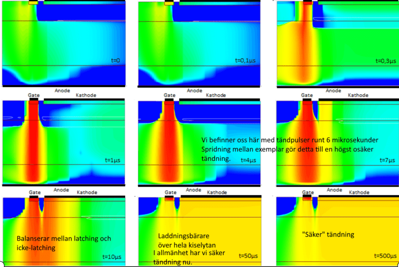
 
Thks Chuck. No this is not a phase controlled thyristor circuit.
Its purpose is to short out the rotor winding during start so it serves as a temporary amortisseur winding. When speed gets close to synch, there is not much voltage in the winding, the thyristors then are left open and the ordinary excitation takes over.

The trig unit senses the voltage and fires the shorting thyristors during start. There are no phase angles involved, just sensing the instantaneous voltage level of the induced sine. The levels are doing fine and the trigger pulse is in its right position. But the gating pulse is simply too short to trigger and latch reliably.

The "thermal" image is not from a camera. It is from a simulation made by Semikron, the company that delivers the thyristors.

Gunnar Englund
--------------------------------------
Half full - Half empty? I don't mind. It's what in it that counts.
 
OK, Chuck. I guess that you found that out, yourself. Your comment just disappeared..

Gunnar Englund
--------------------------------------
Half full - Half empty? I don't mind. It's what in it that counts.
 
6uS is more than enough time if you hit the gate hard enough. I'm doubtful that pulse you're showing is hard enough.

I just happen to have a synchronous setup in test. The circuit we use to trigger a 100A brick SCR will trigger it in about 1uS, but it's applying about 5A peak to the gate.

You shouldn't need any energy storage...
 
Thanks. It is only 1.5 A in "my" case.

If you need 5 A for a 100 A tyristor, I probably need more for a 410 A device.

Yes, an energy store is necessary. You cannot produce a 5 A pulse, not even a 1,5 A from a voltage divider without having lots of heat. The R[sub]i[/sub] in the divider needs to be in the order of 10 or 20 ohms with output voltage around 10 V. Feed that divider with 1 kV and you will have kilowatts.
Discharging a capacitor does it easily. But it also needs charging without too much delay. That's why the power loss is quite high, also when there's a capacitor. But not more than around ten watts. Still too much.

Gunnar Englund
--------------------------------------
Half full - Half empty? I don't mind. It's what in it that counts.
 
Why a voltage divider. Connect the trigger circuit gate to anode.

There doesn't need to be much power loss when the current pulse is around 1uS in duration. Peak power levels may be high, but the energy that must be dissipated by the components is very low. 1/4W resistors can even work here.

A little 410A puck device isn't much harder to trigger compared to the 100A brick device. You're probably talking about a 20mm device most likely, maybe smaller. Really not much harder to trigger than a 100A brick device.

Do you have a circuit diagram?

 
OK, I see. That sounds like a good idea.
No, no diagram. The thing is potted and in a metal box.
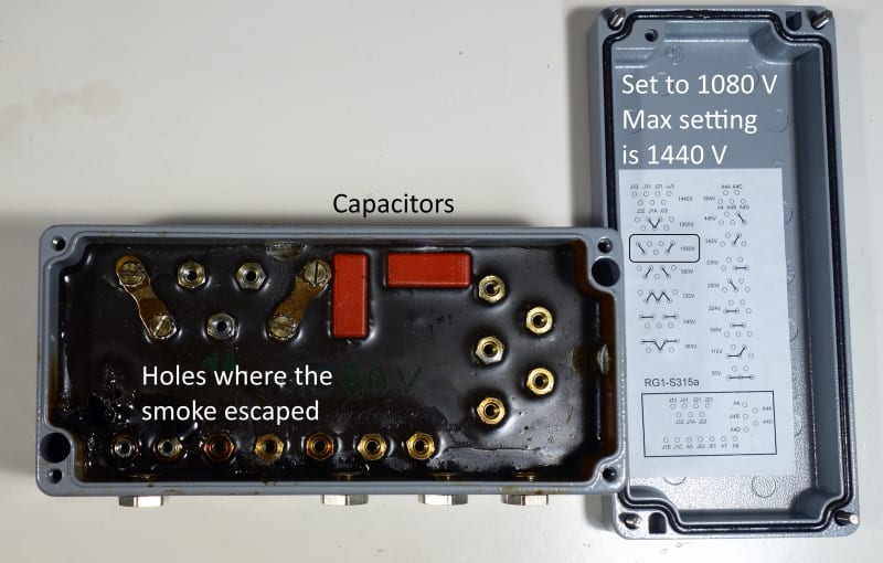
The only diagrams are the connection diagrams. The box looks like this:

NEA_box_not_original_the_German_one_with_hole_for_smoke_w_comments_ytw8fe.jpg


The trigger voltage is set to 1080 V. On another box, slightly different, it was set to 950 V. The user says that it shall be that high so load transients don't start something funny. Like shorting the exciter when in operation. Can't say if that is the truth or not. But it works (worked) well for years with that setting.

A direct connection from anode to gate will start conducting at a few volts. And I can see that it will not be good. But the idea is good - only needs some refinement.

No support from the German company. There have been a few blown thyristors in the past and that's why I was asked to have a look at it. The machine is 20+ years old.

Gunnar Englund
--------------------------------------
Half full - Half empty? I don't mind. It's what in it that counts.
 
Well, you need a series device in the gate to anode connection that doesn't conduct until the breakover voltage, at which point it very quickly begins conducting a decent current. You also need to add a couple of gate to cathode components to make sure the SCR doesn't trigger via noise and to protect the gate against reverse bias.

I know a circuit that works, but it's company information. Just trying to get you enough hints you can get to something that works on your own.

The trigger needs to be occur at value above the peak bridge output the SCR will see while off and motor running or else it would be constantly triggering on.


Yes, I got it. I'll make a copy of the result and show it here. The triggering is still somewhat "noisy" will add a small filter before the OVP. Thanks.

But, tomorrow, I will be looking at an inductive furnace with a thyristor H bridge which also has some problems. So it won't be until later.

Gunnar Englund
--------------------------------------
Half full - Half empty? I don't mind. It's what in it that counts.
 
I mean AFTER..

Gunnar Englund
--------------------------------------
Half full - Half empty? I don't mind. It's what in it that counts.
 
Hello Gunnar

Yes a little post partum posting, after searching and reading on line I decided to pull the post. "Remain silent and be thought a fool, open your mouth and remove all doubt"

Thank you for the clarification on that.

Chuck
 
Wish I was as wise as some..

Gunnar Englund
--------------------------------------
Half full - Half empty? I don't mind. It's what in it that counts.
 
I wish I was half as intelligent as you are Sir, really enjoy your post.

Chuck
 
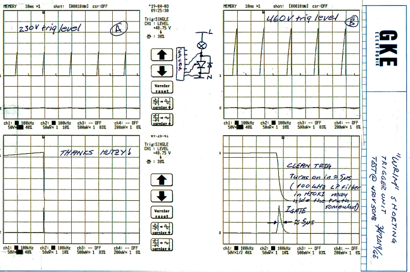
OK, Hutzy. It works very well:

Nea_Hylte_trig_unit_w_gas_discharge_OVP_1_fvz5g5.png


I may have got something wrong. But it works beautifully. Stable, repeatable and low dissipation. And, what I think is important, I have accepted the short gating pulses. Good to have EngTips.

Gunnar Englund
--------------------------------------
Half full - Half empty? I don't mind. It's what in it that counts.
 
The waveforms look good, so you did it a little differently but certainly not wrongly.

It's really quite simple once you get there, isn't it? Glad I could provide the nudge you needed.


Me too. NO, not THAT me too.

Gunnar Englund
--------------------------------------
Half full - Half empty? I don't mind. It's what in it that counts.
 
Status
Not open for further replies.

Part and Inventory Search

Sponsor