Eng-Tips is the largest engineering community on the Internet

Intelligent Work Forums for Engineering Professionals

  • Congratulations waross on being selected by the Tek-Tips community for having the most helpful posts in the forums last week. Way to Go!

1920's era concrete joist designation 1

Status
Not open for further replies.

trekkie

Structural
Sep 11, 2003
17
0
0
US
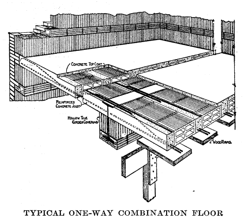
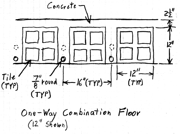
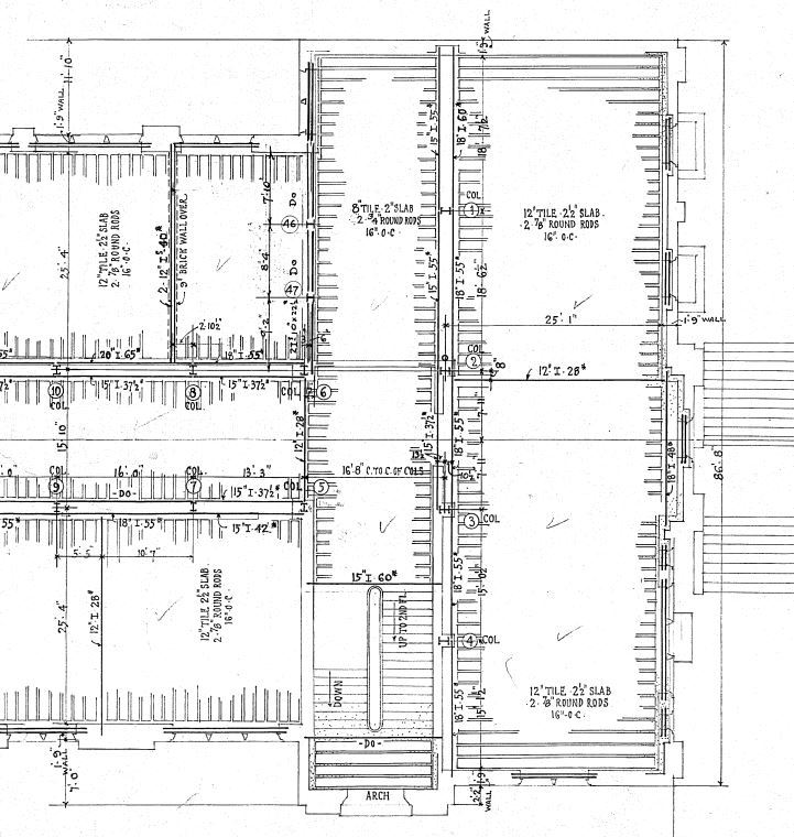
I have an existing 1920s building where the floor framing appears to be concrete pan joists and the designation on the drawings is 12" TILE - 2-1/2" SLAB...Is anybody familiar with that? Is that saying the total depth is 12"? Was there a standard width for these I couldn't find it on the drawings. See the attached image for a partial plan view hopefully it came through, Thanks in advance.


1920s_ypmovf.jpg
 
Replies continue below

Recommended for you

I did not have the time to examine the attachment, but an familiar with that type of floor construction (historic and current) for the U.S. and foreign. The "flat terracotta arch" term seems to describe what I have seen.

I had a unique home in Minnesota built in 1917 and the exterior walls consisted of actual 10" clay tile (cores horizontal) as the structural portion that had a stucco exterior and the interior consisted of full (not nominal) 2x4s, lath and plaster with a "China coat". During some modifications, I measured the 10" clay tile and the dimensions were actual and not modular. Since then, most dimensions of the similar units were converted over time to nominal.

There are many floor systems(floor filler systems) in use in many countries today with both concrete block or clay block used as fillers between the cast in place beams and/or precast beams and the thickness of the topping varied to provide a level finished floor surface.

The filler systems are still used in some countries (Eastern Europe) even for roofs with a slope. The precast beams carrying the fillers and the topping are a standard product and the topping varies depending on the finished surface requirements.

When I looked at the drawings provided on this site, It appeared that the height controls were dictated by the long span and the topping thickness varied depending on the elevation of the "beam" seats. - just a guess.

Dick

Engineer and international traveler interested in construction techniques, problems and proper design.
 
This is not an arch system - it is exactly what stevenspm states - using tile as a stay-in-place form.

The 12 inches is the vertical depth from the bottom of the concrete joist web up to the bottom of the slab. Then you have 2 1/2" of slab for a total joist height of 14 1/2".

It appears from the plan you provided that each rib has (2) two 7/8" or 3/4" diameter round rods as bottom reinforcement spaced at 16" o.c. This implies that the ribs formed by the gaps in the tile forms are 16" o.c. I don't see where the rib width is provided but you could probably very easily verify that at the building. There might also be other notes or typical joist details that might indicate the horizontal layout of the joists.

Just as a side note - the usual challenge with these joists are the shear capacities - usually they were not supplied with any stirrups or ladder bars to provide Vs to supplement Vc. So you are stuck with Vc only and it seems that engineers prior to the 1950's didn't really have a good grasp of shear capacity.

Check out Eng-Tips Forum's Policies here:
faq731-376
 
JAE & stevenspm have convinced me this is not "Terra Cotta Arches", but a "One-Way Combination Floor" per JAE's description:

One-Way_Combination_Floor_z1suvb.png


For these floors, tile width seems to have been standardized at 12". Various heights were available, including both 8" and 12". Common concrete joist widths (between each tile) were 4", 5" and 6". A 4" joist would put the rebar at 16" O.C., as specified. The callout of 2 rebar is a puzzle... perhaps they were spaced vertically in the joist.

This is my concept of the detail, see pages 367 through 371 of the 1934 Carnegie Pocket Companion for background info:

Combination_Floor_bx4eqs.png


[idea]
[r2d2]
 
Tile were a very common form of construction in the first half of the 20th century; commercial, institutional and high-end residential buildings frequently used them. Aside from specific companies (lots of info available on the web) you can get generic info from Ramsey & Sleeper's Architectural Graphic Standards, even the 6th edition in the 1960s.
 
Would the 2 bars perhaps be one bottom, one top? I think this will require some minor destructive investigation to find out exactly what is there.
 
I've seen both, hokie66. Usually there was a straight bar and a bent (truss or crank) bar side by side at midspan. In SRE's sketch they are shown one above the other and there's no mention of "crank" bars on the plans.

Your suggestion of minor destructive investigation is appropriate if the more conservative assumption doesn't work after trying first. A small chipping hammer on a couple of joists near midspan would reveal what's there.


Check out Eng-Tips Forum's Policies here:
faq731-376
 
Status
Not open for further replies.
Back
Top