Eng-Tips is the largest engineering community on the Internet

Intelligent Work Forums for Engineering Professionals

2:1 Head straight flange in SEC. VIII, DIV. 1 1

Status
Not open for further replies.

HungM

Mechanical
Nov 3, 2020
12
0
0
TW
Hi,

The following welding detail is for attaching a 2:1 head to a shell. Does ASME BPVC Section VIII, Division 1 prohibit such a configuration?

2024-7-11_%E4%B8%8B%E5%8D%88_12-51-38_ljur2m.png


HungM
 
Replies continue below

Recommended for you

In my opinion Figure UW 13.1 (i) and (j) would apply for case under consideration and it doesn't permit such construction.

The underlying logic for the suggested construction is to add material to thinner section to provide for transition between two thicknesses. In doing so minimum thickness requirement for both head (which is usually thinner) and shell (which is usually thicker) are respected. In the figure section marked as Straight Face (SF) is a cylinder (geometrically shell starts at TL already and not at SF as marked in figure) whose thickness should be calculated using the same calculations which are used for shell. So, if shell requires minimum of 25 mm one can't have thickness less than 25 mm in SF region.
 
Hi, gnc89 & r6155,

Thank you for your comments. In this case, the required thickness for both the 2:1 head and shell under internal pressure is nearly 10 mm. However, under full vacuum conditions, the head requires about 13 mm and the shell requires 23.5 mm. When looking into UG-33(i), it states, “The required length of the skirt on heads convex to pressure shall comply with the provisions of UG-32(k) and UG-32(l) for heads concave to pressure.” So I referred to UG-32(k) and found the last sentence, “When a skirt is provided, its thickness shall be at least that required for a seamless shell of the same inside diameter.”

2024-7-11_%E4%B8%8B%E5%8D%88_10-41-34_yi1z9a.png


Therefore, my query is if I have the SF as marked in the figure, and the thinner portion (19 mm) of the SF also meets the required thickness for internal pressure conditions (i.e., 10 mm), could I say the straight flange meets the external pressure equirements in the Code?

HungM
 
Hi Hung,

The section marked with SF whose length is 100 mm in figure is part of cylinder(shell) geometrically and hence it needs minimum thickness of 23.5 mm. It doesn't matter if we manufacture is as part of shell or head, it is cylinder and it needs to be at least as thick as the shell. When the code says 'at least that required for a seamless shell of the same inside diameter' it is implied as maximum of thickness required for internal/external pressure or any other load case for that matter and not just internal pressure. Hope this clarifies your doubts.
 
Hi, gnc89,

Thank you for your explanation; I appreciate it. Actually, we inferred the same thing as you – the Code implies that the S.F. should have the same thickness as the shell. In the case of a hemispherical head, Figures UW 13.1 (i) and (j) apply. But for a 2:1 head, if the S.F. is to have the same thickness as the shell, then a tapered transition doesn't exist because the S.F. has the same thickness as the shell. Does that make sense? I’m not so sure...

I’m trying to figure this out, no offense intended.

HungM
 
Keep in mind shell side does not need to have the same thickness through out.
First is to make sure the weld is sway from the formed head which has high residual stress. That is why code sets a dimension for that.
Then model head without straight flange, and model 100 long straight flange with 13 mm thick as a shell, then 25mm for the rest of the vessel. Run in any software for internal and external pressure, Compress or POV Elite. If no issue, you are good to go.
The major concern in code is stress and safety.
 
OP,
....But for a 2:1 head, if the S.F. is to have the same thickness as the shell, then a tapered transition doesn't exist because the S.F. has the same thickness as the shell. Does that make sense? I’m not so sure...

You are correct. But to allow SF is always better to keep the welding stresses away from the knuckle as jt1234 pointed out.

GDD
Canada
 
The sketch has the wrong definition of straight flange that diverts ALL people to wrong direction.
Straight flange is from TL to the weld, and then weld to a taper shell section and to 25 mm section. Nothing wrong with the design but just to carefully model every section and run internal and external analysis. As long as stress passes, and the weld has sufficient distance to TL, you are good to go.
 
NO, NO
@jt1234
You are also confused.
(OP)'s sketch is 100% incorrect. Forget it.
Make the right sketch and you can see that SF DOES NOT EXIST,

Regards
 
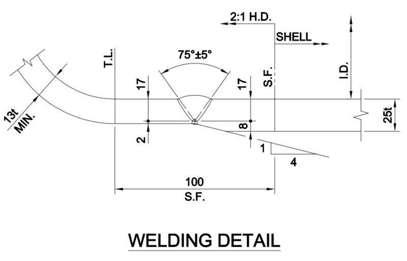
r6155, SF does exist but the sketch does not show the SF location correction.
Hunm(OP), the SF is from TL to weld. Your sketch is wrong. It may be 1.5" or 2". There are other issues:
1). You say 10 mm is good for head and shell. So you can't say 13 "min" for head. If you do so, vendor will provide 15, 16 or more "nominal" to meet your 13 min. It is ok you ask 13 min, but do understand the meaning of minimum and nominal, and what vendor will provide.
You shall specify "10 min after forming, nominal by vendor", and vendor will use 13 or more nominal.
2). Your design is ok as long as it passes code analysis, but very awkward. It is not industrial common practice. You are wasting the money and create unnecessary problems:
Common practice is to use vacuum stiffening rings to save cost and weight. So you shall design for 10 min head / 10 shell with certain amount of stiffening rings. (vendor will use 13 or more nominal for head).
Or 12 min head/12 shell to reduce the amount of stiffening ring ( vendor will use 15 or more nominal for head)
Or 13 min head /13 shell with stiff rings. (Head will be 15 or more nominal)
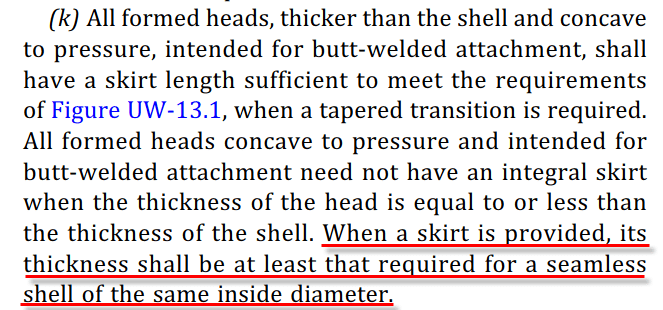
or 15 nominal head/15 shell with less stiff rings. (min thickness after forming will guarantee to meet internal pressure), or 15 min head/ 15 shell

On and on, lots of combinations.

So what stop you from using vacuum stiff rings ? In my experience, only low alloy 2 1/4Cr-1 Mo in 1000F that we don't like to use external stiff rings. This is purely based on personal experience. Code does not prohibit using stiff rings.

Your design also crates extra weight for lifting, more seismic loading and bad for foundation design if this is a big vessel.
Do I have such case as you have ? Yes I do. A 300 feet tall tower with heavy wind, that the bottom shell section must be much thicker for the wind bending moment than the connecting head. So I state nothing wrong with your design, but if it is necessary ?


Hi, All,

Thank you for all your valuable opinions. To avoid challenges from the client and local jurisdiction in the future, we have decided to use the same thickness for the 2:1 head as the adjacent shell (25 mm). We are in the DDE phase, so there is time to reflect this. However, personally, I still have some unresolved queries.

The first query is regarding Figures UW 13.1. Figures UW 13.1(i) and (j), which apply only to hemispherical heads. Normally, for a 2:1 H.D., the taper transition will not exist because the SF has the same thickness as the shell. Figures UW 13.1 (k) and (l) apply when the thickness of the head and the shell differ by more than one-fourth the thickness of the thinner section or by more than 1/8 in. (3 mm), whichever is less. Is this inference correct?

The second query relates to PV Elite calculation results. When I modeled the head (with a minimum thickness of 13 mm), SF (50 mm in length with a thickness of 19 mm), and shell (25 mm) in PV Elite 25, it showed no issues. The software provided results contrary to my first query…

HungM
 
Good.
Now more information(I'm curious): diameter, length, material, design pressure and temperature, horizontal or vertical, wind, seismic, etc., etc.
Next time send it to us when you open the post.
Remember: more details = better answers (as Litleinch says)

Regards
 
HungM, the key issue of Fig UW-13.1 is two parts:
1. how long the taper section must be.
2. center lines of head and shell must be within the limit to prevent too must over twisting. It does not matter which is thicker or thinner. Also you will need to identify where the weld. Code will not tell you because it is end user to locate the weld.

If you input 19 for SF in PV Elite, that means to the program you are using 19 nominal plate to achieve 13 min head after forming. Head for internal and external pressure will be based on 13. SF which is part of the shell will be based on 19 for internal and external pressure. The total weight will be based on 19, not 13. Hope you understand how the program is doing. If no error message, you are good to go.
 
gnc89 said:
So, if shell requires minimum of 25 mm one can't have thickness less than 25 mm in SF region.
gnc89 said:
It doesn't matter if we manufacture is as part of shell or head, it is cylinder and it needs to be at least as thick as the shell.

This is false. A shell with no RT (E=0.7) will be thicker than a straight flange (skirt) designed as a seamless shell (E-0.85).
 
david339933 said:
A shell with no RT (E=0.7) will be thicker than a straight flange (skirt) designed as a seamless shell (E-0.85).

I agree. Didn't think of effect of E on thickness calculation. Thanks for reply.
 
Status
Not open for further replies.
Back
Top