Eng-Tips is the largest engineering community on the Internet

Intelligent Work Forums for Engineering Professionals

2 Point Center Lift vs 4 Point Corner Lift

Status
Not open for further replies.

MikeC88

Mechanical
Jul 27, 2017
24
0
0
GB
Hello All,

I am hoping to draw on someones expertise on lifting ductwork.

I have a piece of duct work to lift offshore ~ 3.7m in length, 1.8m wide, and 1.2m deep: Mass ~1000kg, which for intents and purposes can be treated as a cube with a reasonably central COG.

My original design utilised 4x lifting lugs, designed with permissible stresses in line with BTH-1 with Nd=6, with a vertical lift. The 4x lugs are located towards the 4 corners of the structure, on the upper surface (COG below lugs). One assumption made was that in reality, the weight would be taken by only 2 of the lugs.

To help with installation we have installed an additional set of lugs, based on the same design as the 4x corner lugs at the center of the duct work, roughly in line with the COG.

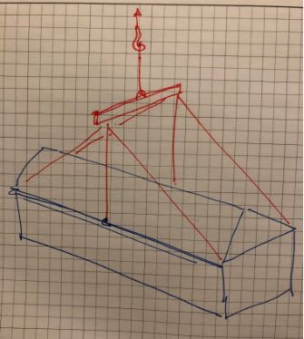
It has now been queried whether we could lift the structure from the 2x central lugs to a single point. It has been proposed that the 4 corners are then attached to the single point not to weight bear, but to assist with keeping the duct work level during the lift.

The mechanical design limits the lifting angle well below any value at which permissible stresses are exceeded, however I am hesitant to recommend this lifting arrangement, but am unable to justify why not other than the increased consequence of 1x lug/strop failing, and potentially stability issues?

Can anyone provide any pointers as to whether this type of lift would be permissible, whether it is recommendable, or any potential pitfalls that I need to be aware of/investigate.

Thank you in advance for any help offered, I look forwards to hearing peoples thoughts.

Mike
 
Replies continue below

Recommended for you

If the ductwork itself can handle being lifted by two points, and you can rig an point or two to an auxiliary line, that may in fact be a more controllable lift than 4 fixed length lines. Although if the CG is near the center, that's probably not a big concern.

My experience with ductwork is that it mostly is not destined for lifting, so a 2 point pick may not work. But if it's for offshore use, that improves your chances.

----
just call me Lo.
 
Hello Lo

I've attached a sketch for reference, but understand the lifting from center should be acceptable - however there will be increased stresses in the duct structure itself, that need to be checked out.

Thanks for your thoughts on this matter
 
Yes, especially if you can put those lugs anywhere along the beam to match the CG, I would feel good about lifting with two point rigging, with an additional one or two points of contact for load control. Depending on your crane and lift plan, those may be auxillary lines for tilt, tag lines to prevent rotation about the vertical axis, etc.

The I beams, if added for the lift, also will help with the duct stresses.

I think you're in good shape.

----
just call me Lo.
 
In your sketch, is that a lifting beam or a spreader beam? A lifting beam would imply (in my line of work anyway) that you have a single line from the beam to the crane hook. Your dotted red lines can handle the load imbalance between the duct work and the lifting beam, but there is nothing stopping the lifting beam + duct work assembly from rotating about the lift point on the top side of the lifting beam. When you had a (4) point pick up from the beam to the duct work, the entire assembly was more stable. Can you add the rigging from the lifting beam to the crane hook on your sketch?

EDIT: I thought about this again and drew it out, I was wrong above. The ductwork will rotate slightly so the COG aligns with the crane hook, the lifting beam will rotate slightly with it, but remains stable. But thinking about this further, to lift this as proposed in your sketch, couldn't all of the red riggings go directly to the crane hook and skip the lifting beam? Or maybe turn the lifting beam 90deg and keep your main lifting lines plumb - see rough sketch.

duct_lift_j0dj6f.jpg
 
The 2-point pick can work if you check the out-of-plane load on your lug since it will tend to dip so the COG finds itself beneath the hook. Adding the 4 additional points is gravy that will help prevent, but not eliminate the dip. Have you checked the 4-point pick with in-plane and out-of-plane loads on the lug plate? How thick is your lug plate? Are you designing to the plastic capacity or elastic capacity? It might all be a moot point for 1000 kg.
 
Hello All,

Thanks for your continued input,

Lomarandil - The central lugs are in line with the predicted COG. The I beams are part of the duct structure, originally to support two overhanging platforms, that are now being installed separately.

CANPRO -
In my sketch the green beam represented a (very) simplified spreader that I intended on using for the original lift.

The suggestion has been that we avoid the use of spreaders and lift to a single point, denoted by the red lines ( I should have added separate hook to avoid confusion/done two separate drawings for clarity). As you suggest in your edit the request is to skip the spreader all together.

Skeletron

Lug plate is 15mm thick - and the design has been to keep permissible stresses within those specified by BTH-1 (As there were a few unknowns at the point of design I based design on a Cat C lifter so the design factor utilised is Nd=6.

The COG is in line with the central lugs, 3700mm span, so out of plane forces should be minimal -my design incorporates stresses for 5° out.
But it is slightly off center width ways, ~70mm offset from center on 1800mm width.

It is to avoid out of plane loading (and the use of a spreader) that the suggestion has been made to lift from central lugs

Thanks again for the input so far, it has been very useful!
 
MikeC88:
Just some food for thought… It sounds like the ductwork is basically hung from the two side beams, but they should be checked both vertically and laterally for the lifting loads. Someone should calc. the CG and you should place your lifting pls./padeyes at the longitudinal CG, even if not the exact center of the length of the ductwork. Put your lifting pls. on the top flg. of those side beams, and right over and parallel to the beam webs, and leaning in to the two planes of the two lifting slings, +/- a few degrees. These two lifting pls. are easier to fab., fit up and weld than the pls. btwn. the flgs. and with such large torsional eccentricity. For such light loads, make all six lifting pls. the same detail, although the four corner pls. could have larger lifting forces parallel to the beam webs, than the two center pls. Cut the bot. edge of the pls. to the proper angle (leaning in) and fillet weld on the two sides. Don’t weld around the ends because you will as likely as not cause a stress raiser notch at the pl. edge corners. If you just lift the ductwork free of the ground, you can adjust the lengths of the two main slings and the four slings to the corners so that you are lifting the piece level and basically ready for installation when lifted into place. If you are lifting off of or from a barge, watch out for some potential dynamic loading. Talk with your rigger about what sling lengths and lifting hardware is available, this will make your design easier and his job easier too.
 
dhengr

Thanks for the food, it has definitely inspired some thought!

Central lifting eyes are in line with CoG.

Agree that structure needs to be investigated, I will be making this recommendation.

With regard to manufacture, I will have to take these points on board, the lugs are currently welded in between flanges. If structure study finds the eccentricity to cause problem we will have to do as suggested. (I will also take on board for future)

Thanks for the assistance guys, it has been invaluable as ever!
 
Status
Not open for further replies.
Back
Top