Hello All,
I am hoping to draw on someones expertise on lifting ductwork.
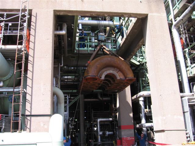
I have a piece of duct work to lift offshore ~ 3.7m in length, 1.8m wide, and 1.2m deep: Mass ~1000kg, which for intents and purposes can be treated as a cube with a reasonably central COG.
My original design utilised 4x lifting lugs, designed with permissible stresses in line with BTH-1 with Nd=6, with a vertical lift. The 4x lugs are located towards the 4 corners of the structure, on the upper surface (COG below lugs). One assumption made was that in reality, the weight would be taken by only 2 of the lugs.
To help with installation we have installed an additional set of lugs, based on the same design as the 4x corner lugs at the center of the duct work, roughly in line with the COG.
It has now been queried whether we could lift the structure from the 2x central lugs to a single point. It has been proposed that the 4 corners are then attached to the single point not to weight bear, but to assist with keeping the duct work level during the lift.
The mechanical design limits the lifting angle well below any value at which permissible stresses are exceeded, however I am hesitant to recommend this lifting arrangement, but am unable to justify why not other than the increased consequence of 1x lug/strop failing, and potentially stability issues?
Can anyone provide any pointers as to whether this type of lift would be permissible, whether it is recommendable, or any potential pitfalls that I need to be aware of/investigate.
Thank you in advance for any help offered, I look forwards to hearing peoples thoughts.
Mike

