Continue to Site

Eng-Tips is the largest engineering community on the Internet

Intelligent Work Forums for Engineering Professionals

  • Congratulations SDETERS on being selected by the Eng-Tips community for having the most helpful posts in the forums last week. Way to Go!

2 times line frequency in vibration reading 5

Status
Not open for further replies.

ravindranathan

Electrical
Sep 30, 2006
35
What exactly is meant by "2xLine frequency"in motor vibration readings?
Why is it more prevalent in 2 pole motors?
 
Replies continue below

Recommended for you

2xLine frequency is caused by Magnetostriction. It is also present in transformers.

2xLine frequency may be confused with 2xSS on 2-pole motors, since the two frequencies are close together. The frequencies can be separated by high resolution spectrum (FFT) or by Time Synchronous average spectrum using a Tachometer signal for shaft speed reference.

Walt
 
Magnetostriction is often a dominant cause of 2*LF in transformers. It may be a factor in motors, but I believe it is not as much a contributor for motors as it is for transformers due to difference in geometry. Specifically in transformer there can be a given leg of the core which carries only one phase flux. The leg getting longer and shorter from magnetostriction causes vibration. In a motor the core backiron forms a circle with flux from all three phases flowing at different parts of that circle and in fact the slotting tends to make the backiron flux a rotating sinusoidal function of poles*angle. Changes in length associated with one phase are cancelled by those of another phase so no change in circumference of motor core from magnetostriction. Also there are competing sources of 2LF in motors that do not exist in transformers due to airgap forces....

I believe the biggest source of 2*LF in motors is deformation of the stator by the rotating fundamental mmf wave (which places an attraction between rotor and stator at each pole). In 2-pole motors since the arc between poles is longer the stator core is typically less resistant to deformation by that force.

It is often said that rotor off-center within the airgap (static eccentricity) may cause increased 2*LF. Oddly there is a math analysis that says this is not the case under certain reasonable-sounding assumptions (no saturation of iron, infinite permeability of iron, no homopolar flux). That math analysis does suggest the presence of a constant unbalanced magnetic pull in presence of static eccentricity, but not a 2*LF component of that unbalanced magnetic pull. I leave open the possibility that the particular math model doesn't always match the real world.

I'm interested in hearing other comments about this topic...


=====================================
(2B)+(2B)' ?
 
2X is called the torque pulse frequency. All AC motors produce a 2Xline frequency vibration since there are two peaks in a cycle and the torque is 'unidirectional'.

Possible causes of high 2X - rotor eccentricity, stator eccentricity, resonance etc.

2 pole motors are more susceptible for this 2x vibration due to weak magnetic field distribution.

Muthu
 
I was looking forward to your input kumar / edison123. I was going to ask if you have ever actually seen a case where 2*LF vibration was unmistakably tied to static eccentricity airgap problem (fixed the vib by correcting the airgap). I ask because it is intersting to me that this is so often repeated as a cause, and yet there is a math analysis that suggests that is not the case (under some assumptions worthy of discussion). You can see some of that here. I think it was page 169 at that link where they stated that but I'm not sure.. my viewing limit expired. If your viewing limit expires, a similar article it is available for free to members of IEEE Industrial Applications Society here. The homopolar flux constraint is what makes the math model act different than most peoples' intution. On the question of whether uneven airgap really causes 2*LF in practice, I have a little bit of experience on both sides but not enough to make a decision based on my own direct observations. And by the way, I consider foot sensitivity of 2*LF vibration a different issue that is not related to airgap.

Regarding torque pulsation. Math tells us that single phase motors and unbalanced three-phase motors have torque pulsation at 2*LF. But it should not exist for balanced three phase motors. Rather than suggesting torque pulse as a cause maybe we can mention unbalanced voltage (if we are talking about 3-phase motors)

I don't claim to be an expert on this subject of 2*LF vib, but it is something I have been very interested in lately. So interested to hear more comments.

=====================================
(2B)+(2B)' ?
 
One piece of data gathering I have been meaning to do and haven't gotten a chance yet. Using a 2-channel vib analyser, check the relative phase of the 2LF vib at two locations 180 degrees opposite. If the phase of the vibration is 180 degrees opposite when corrected for sensor orientation, that suggests the rotating stator deformation and seems to rule out most other causes pretty convincingly. If the phase is the same, it's not quite convincing one way or the other to me for geometrical reasons (the rotating wave could also give rise to a rocking motion due to the asymmetric support stiffness of a horizontal mounted motor). Check at both bearings and at axial center of stator.

=====================================
(2B)+(2B)' ?
 
pete - In a few 2 pole motors (from 700 to 900 KW) with anti-friction bearings having perennially high 2X vibrations (more than 5 mm/sec), I have corrected (to less than 1 mm/sec) by proper re-centering of the end bells by machining, in which bearing seating areas were found eccentric by about 0.3 to 0.4 mm with respect to the stator seating rabbet. Such motors are rare case of poor manufacturing by OEM. I can confirm air gap eccentricity can cause 2X vibration.

Muthu
 
Thanks Edison. Those are some good data points. It leads me to wonder where the model of that linked paper would break down. I believe the math is sound (I have seen another author independently analyse the same question under the same assumptions and come to the same conclusion). So I think the relevant problem would have to lie in the assumptions
[ul]
[li]1 - One assumption they talk about is no homopolar flux. Let's say 2-pole motor, look at the moment in time when stator field N pole is adjacent to minimum airgap and S pole is adjacent to max airgap there is more mmf to drive flux across the airgap from N pole than from S pole. But since flux must flow in loops, there cannot be more flux crossing the airgap from the north poles to non-zero total flux crossing airgap unless that flux flows somewhere outside the airgap. That flux would be homopolar flux and the homopolar flux path would have to be through the rotor / shaft to the very small contact area at the bearings (high reluctance), then return to the stator core through steel structural components. Additionally my thinking is that the frequency of the homopolar flux is line frequency so the eddy currents induced by flux flowing in unlaminated structural iron might cause a pretty significant reluctance in iron. It seems fairly reasonable to assume this homopolar flux component is 0 (due to high reluctance of the bearings and possibly the structural iron) as the authors did, but who knows. While these authors assumed open circuit to homopolar flux, many authors assume short circuit to homopolar flux as a simplifying assumption - NOT because it is more accurate but because it is waaay easier to calculate the fundamental flux under homopolar short circuit assumption... it is simply proportional to rotating sinusoidal mmf divided by airgap distance. In contrast enforcing 0 homopolar flux significantly complicates the model as you can see at the link. I suspect the real world gives a homopolar flux path with a reluctance somewhere between short circuit and open circuit... seems qualitatively closer to the open circuit side but how to quantify that deviation would be a challenge. [/li]
[li]2 - Another assumption is infinite permeability of the iron. I don’t see the infinite permeability assumption is going to change anything… to the extent that the iron is fairly symmetrical we can simply model the iron reluctance as a uniform increase in airgap dimension around the circumference, which would not change the results of the model other than having to recompute nominal airgap detla0 and eccentricity epsilon. [/li]
[li]3 - Another relevant assumption (if we relax the infinite permeability) is no iron saturation. I don’t see saturation effects are going to change the conclusions much eithr… saturation effects would be most noteable where the flux is highest at locaton of minimum airgap, so effectively it increases the effective distance the flux has to flow at that minimum airgtap location and as such would seem to reduce the tendency for 2*LF unbalanced pull on rotor toward the point of minimum airgap (as compared to a model that does not include saturation).[/li]
[/ul]
By process of elimination of #2 and #3, my uninformed gut feel fwiw is that #1 the homopolar flux assumption is the more important one (the one whose violation might cause 2*LF component of unbalanced magneti pull). IF that were really true, then design features which increase the reluctance of the homopolar flux path would reduce tendency for 2*LF vibration in presence of eccentric airgap.

The bearing insulation which is sometimes added to prevent bearing currents might be one such design feature.... although I don't have a feel for how big reluctance of structural iron carrying 60hz is, compared to the bearing and any small adjacent insulating gap.


Haha, well 2*LF vib has always been of interest to me and moreso recently. So I took the opportunity above to explore some things that have been on my mind about 2*LF which I’m sure is not what the op was looking for.

For the benefit of OP, I’ll summarize the two most commonly cited sources of 2*LF from the literature:
1 – asymmetric airgap (static eccentricity)
2 – deformation of the stator core caused by the rotating fundamental mmf wave

I think above is a reasonable summary, and anyone wanting a 50,000 foot view should stop ….

=== WARNING RAMBLING IN-THE-WEEDS AHEAD ===

Since the thread is probably otherwise dead and I’m on a roll and enjoy talking about this (maybe it’ll bring out some comments I can learn from, or maybe one or two people will be interested in what I’m saying), I’m going to use this thread to explore some more thoughts and experiences about 2*LF vibration, focusing on the 2nd of the two 2*LF causes above which we didn’t talk about yet. I would argue the 2nd one is a common cause of 2*LF which often cannot be corrected and can form the basis for foot-sensitivity of 2*LF vibration.

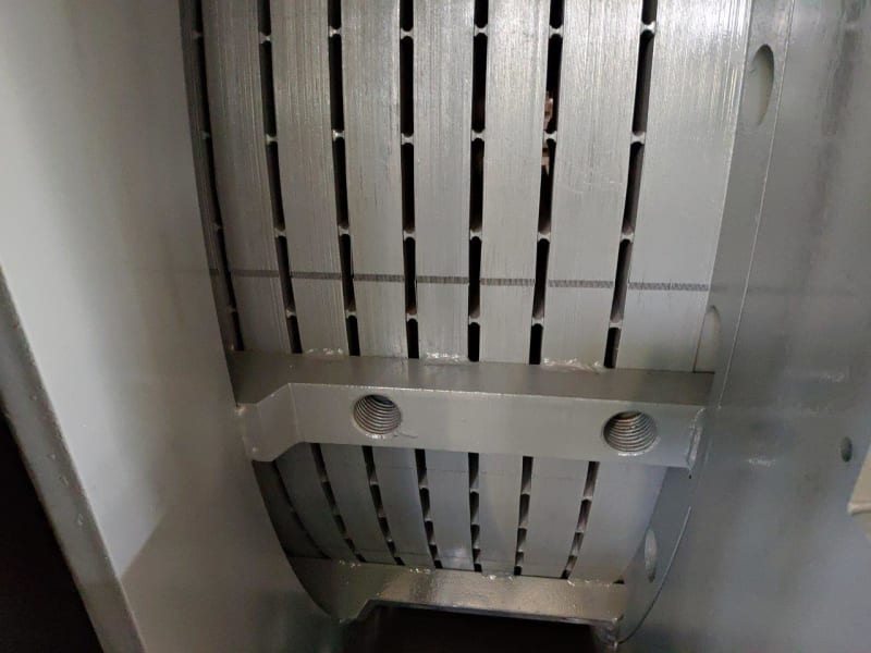
What do I mean by “2 - deformation of the stator core caused by the rotating fundamental mmf wave”? You’ve probably seen pictures of it before. It applies even when rotor is perfectly centered. For a 2-pole motor, the stator core is bent into something like an oval shape rotating at 3600rpm in 60hz land, so two peaks per revolution (of stator field) pass a given point and if you had an acceleromter on that point you’d see 120hz. If you have a 4-pole motor, the stator core is bent into a shape like a smooth 4-tooth gear. With field rotating at 1800rpm, you again see 120hz motion at a given point on the stator core. This is said to be a more prevalent vibration source for 2-pole motors because the arc width of the 2-pole is longer so it is less resistant to bending in that shape than it would be to bending into a 4-pole / 6-pole etc shape.

The vibration appearing on the stator core from this rotating stator core deformation can be different (higher) than what appears at the bearing measurement. Example CURRENT AND VIBRATION MONITORING FOR FAULT DIAGNOSIS AND ROOT CAUSE ANALYSIS OF INDUCTION MOTOR DRIVES by William Thompson in proceedings of the 31st turbomachinery symptosium
Just under figure 9, you'll see they measured the stator core back-iron at two locations and saw 2*LF vibration was 4.5 times as high on the core as on the bearing housings.

It might be surprising for to you to learn above that the 2*LF vib is higher on that stator core is higher than on the bearing housings. To understand why that can occur, a few things to consider… First remember the electromagnetic force we’re talking about are acting directly on the stator core. Second let’s remember that this particular version of 2*LF (from rotating deformation of the stator core) is not accompanied by any unbalanced magnetic pull on the rotor. So it doesn’t load the bearings and won’t show up on the bearing housing that way. The only other way for the vibration to show on the bearing housings is by interaction between stator core and stator frame, which in turn holds the bearings. So exactly how does the core interact with the frame?
[ol A]
[li]On a large horizontal sleeve bearing motor, that interaction is typically minimal… the core is often bolted to the bottom of the frame and not rigidly attached to the sides, so the stator core can vibrate without transmitting that vibration to frame which holds the bearing housing.[/li]
[li]On a typical smaller NEMA frame horizontal motor things are more variable and trickier. I was told by an old Siemens motor engineer that it is an important part of the frame design that they keep the core deformation forces from causing vibration at the monitored location of the bearing housings. That is a challenge when you think about it, how is the frame which is supporting the core and intimate contact not going to move from those core forces. He said there were various frame design “tricks” that they use to accomplish that. He also mentioned that some TEFC motors of a cheaper design where the core was interference fit into the frame without ribs accomplished the desired suppression of bearing housing 2*LF in a non-robust way which was very sensitive to the interface pressure generated by the design interference. BUT if there were minor distortion from a soft foot, it effectively changed the carefully selected interface pressure/geometry and destroyed the optimization which they had designed specifically to hide the 2*LF from the bearing housings. In other words, a soft foot condition caused an increase in 2*LF vibration on these motors NOT because the airgap was distorted but because it altered their sensitive design in a way that allowed the 2*LF originating from rotating stator core deformation forces to appear on the bearing housings.[/li]
[/ol]
Blasphemy you say, everyone knows the airgap gets distorted by a softfoot and that what causes the common foot-sensitive 2*LF vibration on 2-pole NEMA frame motors. But how much does soft foot really change the airgap? I would say the stator frame has orders of magnitude higher bending resistance (bending moment of inertia) than the foot. Think about a 100hp 2-pole horizontal motor... Let's say the feet are maybe a 3/4” thick by 3” wide bar, whereas the stator frame might resemble something like a 1/2” thick cylinder of diameter 18” (already waaay stiffer as a calculation would easily prove... bending moment inertia of a hollow cylinder proportional to Diameter^4 vs beam proportional to thickness^4 with different coefficient but the factor [18/0.75]^4 dwarfs the difference in coefficient) plus a bunch more metal around the bottom and possibly more supporting structure inside. So the foot is going to do most of the bending, not the stator frame. Ruling out stator frame bending... maybe soft foot causes the endbell bolts to stretch or the endbells to got repositioned/distorted to a point that the rotor bends? First of all I don't see how that happens without the stator bending. Second of all I would point out there is some misalignment play in the bearings so there is not even any bending moment on the rotor until you exceed that play in the bearings. So my best guess is that any change in airgap from tightening a soft foot is going to be a small fraction of the foot movement. And by the way foot movement to affect 2*LF can be very low…. 0.002” is a typical acceptance criteria but I have seen feet with less deviation than that (as measured by feeler gage all around the interface between foot and base) which still show the foot sensitivity of 2*LF vibration.

Aside from my guesses about how much soft foot can affect airgap, an enterprising motor engineer on maintenanceforums.com tried to measure it as discussed here and in attached article
"Deformation of airgap due to soft foot" . His conclusion was that the change in airgap was small and not enough to affect 2*LF vibration. I posted this info on another forum and there were some critiques of the measurement methods. It’s not an easy thing to measure on a NEMA frame motor (generally only larger motors have ports for this purpose). If I were going to do it I’d look for a suitable motor that has access all around the airgap from the end even with the motor assembled. We have a couple of horizontal open DRIP proof motors that have access to check airgap through the vent ducts, but only at the bottom half of each endbell. Maybe there is an OPEN (not dripproof) motor that has access to the airgap all around the circumference (anyone who has access to such motor feel free to try it and let us know).

So in my opinion, the soft foot doesn’t change the airgap much. You may or may not be convinced of that fact, but there’s more…
I have an anecdote from my experience at our plant that is somewhat relevant.

[ul]
[li]In 2003, we ordered seven 100hp 2-pole Open Drip Proof (ODP) motors from a motor OEM factory that happens to be nearby, with a specification that they had to pass our vibration requirements during testing while rigidly bolted down. (That requirement is different than the general NEMA vibration testing spec which allows them to be tested on a rigid or resilient mount… but I would strongly encourage everyone to include that requirement unless you are prepared to be surprised when that motor is run rigidly bolted down for the first time ever... at your plant!). The OEM was used to testing this size motors on a flexible pad, but accepted our rigid spec and expressed confidence they would meet it. When we got to the factory test, they seemed very surprised to see high 2*LF (0.2ips+) in the horizontal direction on their motors bolted down during the test run. The vibration went away with foot loosening, but the spec required rigidly bolted so they had to meet it. They tried three different motors and same results. They spent several days trying to fix it, by getting the airgap perfect (even sleeved and rebored some of the endbells). They planed the motor feet. They moved it to another test stand. I think they even drove it at a different speed with vfd to check for resonances. None of it worked, the 2*LF didn’t decrease very much through all these efforts. They were working under the assumption that the 2*LF must have been coming from airgap asymmetry and their efforts to resolve that did not change the foot-sensitive 2*LF in this case at all.[/li]
[li]Then they had a phone call with an engineer at a remote location overseas. They informed me they were going to cut some slots in ribs between the motor frame and the core (I think this construction ribs between frame and core is more common for ODP than TEFC). They didn't permit me to watch exactly what they did, saying it was some kind of secret. I came back the next day for the run and the 2*LF was almost gone (<0.02 ips I think). Their modification had worked. Trimming the rib between frame and core had fixed the foot-sensitive 2*LF vibration when no amount of centering effort had fixed it. I don't remember if they told me at the time or not but I came to understand that what the modification had done was to somehow change the characteristics of transmitting the force from the core to the frame to the bearings.[/li]
[/ul]
So far just an anecdote, why should you believe me. Recently I came across a reference which bolstered that view that trimming the ribs changed the characteristics of transmitting the force from the core to the frame to the bearings. Figure 11 in UNDERSTANDING THE VIBRATION FORCES IN INDUCTION MOTORS by Michael J. Costello in Proceedings of 19th Turbomachinery conference shows a modification where the ribs between the frame and core were modified for exactly this reason. The caption includes “To limit the transmission of the 120 Hz vibration from the stator core, each of the six ribs were notched as shown in the cross section. This tends to isolate the core from the end frame to which the bearing housings are mounted”. That gives a little insight why it works: the force is transmitted between core/frame gets limited by the modification to a region more in the center of the stator. That reduces the influence on the endbells/brackets which hold the bearings. It seems to be the same thing type of that was done on my seven motors in 2003. Most importantly it is also a direct in-writing acknowledgement of the types of design “tricks” that OEMs may use to try to prevent the vibration / forces from the core from reaching the bearing housing where they would be measured as mentioned by that old Siemens engineer.

Before I leave the subject I want to clarify what I'm NOT saying. I'm not saying #2 above is the cause of all observed 2*LF vibration on bearing housings, nor and I saying that 1 and 2 combined the explanation for all observed 2*LF. Rather, 2*LF is the fundamental frequency of electromagnetically generated forces throughout the machine and we should not be surprised if there are a variety of different ways that it can show up on the bearing housing.

My rambling has come to an end. Maybe it sounds like a half baked combination of anecdotes, links, 2nd hand stories and half-analysed suppositions designed to convince you of a conspiracy theory? If so, all I can say is that I’m not trying to convince anyone of anything, I'm just a man in search of the truth sharing all that I have...my collection of anecdotes, links, 2nd hand stories and half-analysed suppositions ;-)

Any comments?


=====================================
(2B)+(2B)' ?
 
Thanks pete for that interesting Costello piece. 120 Hz force due to air gap dissymmetry (page 3) is the one I am familiar with, especially in 2 pole motors radial.

A soft foot usually shows up as vibration in all 3 axes when we run the motor decoupled in our shop. I have not bothered so far to check if it shows up at 2x since the vibration goes away if we correct the soft foot. May be the next time, I will take the spectrum when the soft foot is deducted.


I have never seen that. Usually, there is an axial key fitted to the frame/rib and the core plates are guided along this key and then locked axially by end pressure plates. The core plates are slide fit along the circumference on the stator frame bore (small motors) or multiple axial ribs around the periphery (medium to large motors). Now a days, thanks to bean counters, the core plates are welded at the back of the core in multiple places making it a pita for repairers like us when we have to remove and repair the damaged core plates. Because cutting a key way is way more 'costly' than multiple welding according to these dumb asses.

Muthu
 
Core seating on stator axial ribs and welded on 11 KV, 9.6 MW BFP motor under rewinding right now at my shop. Thankfully, there is no core damage.

Sembcorp_9.6_MW_stator_core_back_iron_welding_h0kyza.jpg


Muthu
 
You're right that my description of mounting the stator core for sleeve bearing motors was out in left field. There are a variety but not any that mount directly to the bottom that I know of either. The one I had in mind has a single axial support/rib on the frame on each side near the bottom but not on the bottom.

You mentioned that the Costello article discusses force from (1) air gap dysmmetry page 3. It also discusses force from (2) deformation of the stator core caused by the rotating fundamental mmf wave on bottom of page 2 onto page 3 (he calls it "inherent" vibration, apparently because it relates to design and not to centering).

There is also a paper Analytical Approach to Solving Motor Vibration Problems by Siemens. Note there are various versions of this paper available which say slightly different things about 2*LF, but the version I linked describes describes two forms of 2*LF matching the two we talked about. Their comments about the one I called (2) rotating deformation of stator core...
Siemens said:
As can be seen in Fig. 3, for 2-pole motors the electromechanical force will attempt to deflect the stator into an elliptical shape. The primary resistance to movement is the strength of the core back iron and the stiffness of the housing around the stator core, which is restraining the core's movement. On 4 pole motors the distance between the nodes is only 45 mechanical degrees, 1 / 2 that seen on 2 pole motors, thereby making the 4 pole stator core much stiffer to movement resulting in much lower twice line frequency vibration. Calculations on a typical 1000 HP two pole motor at 60 Hz show 120 Hz vibration at the stator core OD of about .12 inches per second, peak, while values for a four pole motor of the same size are only about .02 to .03 inches per second, one sixth to one quarter of this value. This twice line frequency vibration is transmitted through the motor frame to the bearing brackets where it is reduced somewhat in amplitude
They describe all the things I said about it, although I don't believe the amplitudes they cited would be universal (my own experience descrived above for the seven motors with foot-sensitive 2*LF that was not solved by centering is that it was higher than that when measured on the bearings, another paper that I cited measured higher vib than that on the core). They also show the shapes in figure 3 that the stator would be distorted into... ellipitical/oval for 2-pole and 4-lobed for 4-pole. The net force on the stator core is 0, but there are equal/opposite forces that tend to deform the core into those shapes.


Horizontal-only foot sensitive 2*LF on 2-pole NEMA frame motors is pretty common on motors at our plant. It is more often directional (horizontal) than not.


=====================================
(2B)+(2B)' ?
 
I found another article that gives more weight toward the 2nd type of twice line frequency (rotating stator deformation from the fundamental wave, unrelated to eccentricity) and downplays the first (eccentric airgap).

"The Origin of the Electromagnetic Vibration of Induction Motors Operating in Modern Industry: Practical Experience—Analysis and Diagnostics" by Tsypkin in IEEE Transactions on Industry Applications Mar 2017
[you can view it without signing in on google etc simply by swiping up / mousing up on the page to scroll downwards]

Section IV said:
A detailed analysis of electromagnetic force waves in an induction motor performed in [11] allowed the author to make the next important conclusion: the main “force wave is produced by the fundamental flux and cannot be eliminated by making the machine free from any imperfections, e.g., eccentricity, stator/rotor dissymmetry, and saturation.” This force wave has the mode number equal to twice the pole pair number and the force frequency equal to the twice the supply frequency [11].

Later, in practical vibration analysis, an idea was introduced that the major source of motor vibration at twice line frequency is a static eccentric air gap [13]–[16]. Modern training courses and diagnostic charts associate vibration at twice line frequency in induction motors with an eccentric air gap in the motor.

However, a number of special researches performed on induction motors tailored for the artificial change of the air-gap eccentricity [17]–[20] are not confirming this statement. Usually, vibration levels at twice line frequency depend very slightly on the amount of air-gap eccentricity [20].

Analysis of vibration signals as a function of the combination of static and dynamic air-gap eccentricity in three-phase induction motors [21] allowed the authors to make a conclusion that the 100-Hz (twice line frequency) vibration component will be unpredictable and vibration monitoring of this component to assess the degree of static eccentricity may not be consistent and clear.

I'm going to see if I can find those references 11 and 13-20 when I have time to see if there is anything in there that provides any more insight.

=====================================
(2B)+(2B)' ?
 
no, I wouldn't call it that - it applies even for a perfectly centered airgap/rotor. The rotating stator deformation occurs due to the fundamental flux. At the location of each pole the stator is pulled inward causing deformation. As the poles rotate, the deformation rotates. Attached I tried to show it graphically.


=====================================
(2B)+(2B)' ?
 
Electricpete and Edison--thanks a ton for the inputs.You two seem to be encyclopedia on motors.Interesting reads indeed --highly technical though.
 
Can you read the frequency precisely enough to discriminate between mechanically induced vibration and electrically induced vibration?
If you can put the vibration spectrum on a scope beside a 50 Hz or 60 Hz signal, electrically induced vibration will lock with the mains signal while while a mechanically induced signal will drift by the slip frequency.
Or not?

Bill
--------------------
"Why not the best?"
Jimmy Carter
 
Walt Strong has mentioned some info on this in his post at the beginning of the thread.

Higher resolution of the FFT sometimes helps, but that takes longer to collect (collection time at least one over frequency bin width) and may start to hit the limits of your analyser. So it may not be practical depending on how small the slip is...

The smaller the slip, the bigger the challenge to separate the frequencies. So the worst case is no-load, especially large motors. In that case the 2*LF and 2X (on 2 pole) might be so close that they are separated by a small fraction of a cpm (if both were present they would beat slowly over several minutes).

Walt mentioned time synchronous averaging, which is a fairly sophisticated way to separate the signals.

You can also do power down test and see whether the vib goes away immediately (electrical 2LF) or not (mechanical)

I think the techniques for separating 2*LF from the mechanical faults are well understood and agreed on in the vibration world. In contrast the cause of that 2*lf seems not widely agreed on, you'll read different things in different places.

=====================================
(2B)+(2B)' ?
 
Thanks Pete.

Bill
--------------------
"Why not the best?"
Jimmy Carter
 
Status
Not open for further replies.

Part and Inventory Search

Sponsor