TiCl4
Chemical
- May 1, 2019
- 631
We have a 20K pressure washing system installed in our plant. The system is run via a high pressure pump that draws from a water reservoir. On startup, the system starts by recirculating water through a dump valve back to the reservoir. The system then turns on a PI control loop with the output of the dump valve clamped at 21% (~4,000 psi) for ~30 seconds to drive air from the system and allow operators to check for leaks at low pressure. After 30 seconds, operators enable "High Pressure", which removes the clamp and allows the PI loop to control without the clamp. Setpoint is typically 19,000 psi.
Initial settings were P: 0.3 %/%, and I: 0.05 rep/sec. Bias is 0%. The controller is a standard ISA position PID loop.
Valve Position = Kc * (Error + Error * dt/Ti + Td * Derivative) + CV Bias.
The tuning parameters are: P = Kc, I = Kc/Ti,
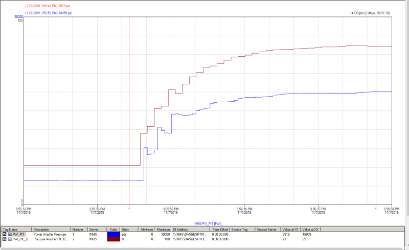
I then tuned it, eventually reaching P: 0.2 %/% and I: 0.3 rep/sec. Reducing P below 0.2 %/% completely eliminated that cycling, and the new controller values have very little (but still some!) cycling. Reducing even further completely eliminated cycling, with a smooth ramp, but resulted in a much longer time to achieve SP.
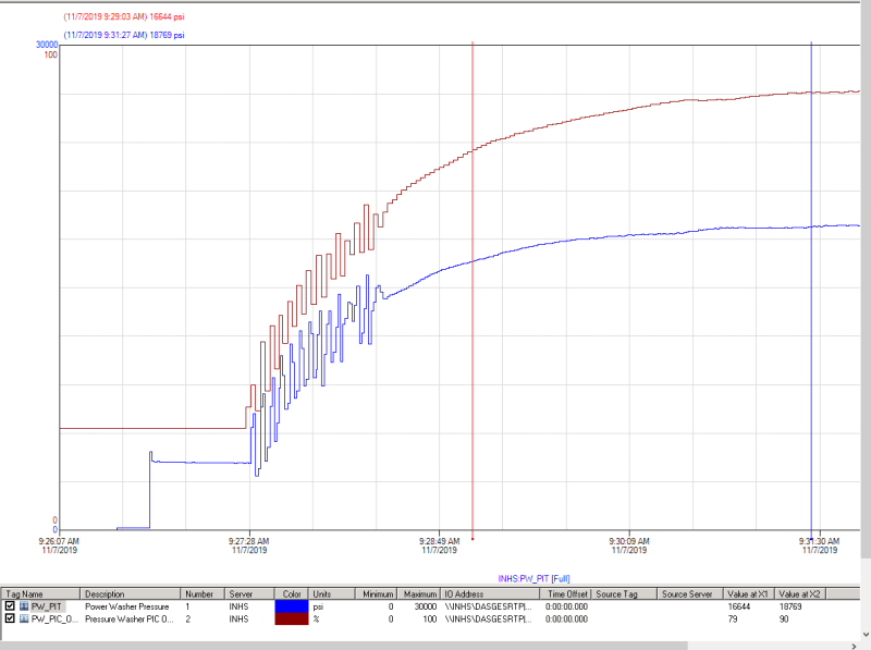
Upon releasing the clamp, the below behavior was observed. The second graph is the final tuning parameters.
Initial:

Final:

With initial settings, the system would cycle, then eventually smooth out. Given the loop is PI only (no derivative control), I don't see any reason that anything would drive the valve back down to make it cycle like it did. The only reason I see as a possibility is this: The sample rate for recording and display is only 2 seconds. It is possible that system pressure went above setpoint due to integral windup during the clamp, causing the valve to re-close quickly, with all of this occurring before the screen or historian updated. It is odd, though, that the historian recorded fairly repeatable values - if the cycling frequency were not the exact same as the sampling frequency, it should have recorded some very high values. The controller also does not have any output rate of change limiter enabled that would only allow the valve to open X%/second
What is causing this cycling phenomenon?
Edit: New information. The current bit as described below is currently set a "0". Since we are starting at 100% error on startup (pressure is near 0 and setpoint is 19,000), the valve is calling for >21% open, leading to BIT 4 setting a negative initial integral value. Does that make sense?
Bit 4: Anti-reset windup action. When this bit is 0, the anti-reset-windup action uses a reset (integral term) back-calculation. When the output is clamped, the accumulated integral term is replaced with whatever value is necessary to produce the clamped output exactly.
When the bit is 1, the accumulated integral term is replaced with the value of the integral term at the start of the calculation. In this way, the pre-clamp integral value is retained as long as the output is clamped. This option is not recommended for new applications. Refer to CV Amplitude and Rate Limits below.
Initial settings were P: 0.3 %/%, and I: 0.05 rep/sec. Bias is 0%. The controller is a standard ISA position PID loop.
Valve Position = Kc * (Error + Error * dt/Ti + Td * Derivative) + CV Bias.
The tuning parameters are: P = Kc, I = Kc/Ti,
I then tuned it, eventually reaching P: 0.2 %/% and I: 0.3 rep/sec. Reducing P below 0.2 %/% completely eliminated that cycling, and the new controller values have very little (but still some!) cycling. Reducing even further completely eliminated cycling, with a smooth ramp, but resulted in a much longer time to achieve SP.
Upon releasing the clamp, the below behavior was observed. The second graph is the final tuning parameters.
Initial:

Final:

With initial settings, the system would cycle, then eventually smooth out. Given the loop is PI only (no derivative control), I don't see any reason that anything would drive the valve back down to make it cycle like it did. The only reason I see as a possibility is this: The sample rate for recording and display is only 2 seconds. It is possible that system pressure went above setpoint due to integral windup during the clamp, causing the valve to re-close quickly, with all of this occurring before the screen or historian updated. It is odd, though, that the historian recorded fairly repeatable values - if the cycling frequency were not the exact same as the sampling frequency, it should have recorded some very high values. The controller also does not have any output rate of change limiter enabled that would only allow the valve to open X%/second
What is causing this cycling phenomenon?
Edit: New information. The current bit as described below is currently set a "0". Since we are starting at 100% error on startup (pressure is near 0 and setpoint is 19,000), the valve is calling for >21% open, leading to BIT 4 setting a negative initial integral value. Does that make sense?
Bit 4: Anti-reset windup action. When this bit is 0, the anti-reset-windup action uses a reset (integral term) back-calculation. When the output is clamped, the accumulated integral term is replaced with whatever value is necessary to produce the clamped output exactly.
When the bit is 1, the accumulated integral term is replaced with the value of the integral term at the start of the calculation. In this way, the pre-clamp integral value is retained as long as the output is clamped. This option is not recommended for new applications. Refer to CV Amplitude and Rate Limits below.
