Continue to Site

Eng-Tips is the largest engineering community on the Internet

Intelligent Work Forums for Engineering Professionals

  • Congratulations SSS148 on being selected by the Eng-Tips community for having the most helpful posts in the forums last week. Way to Go!

20' Tall Pin-Pin Foundation Wall

Status
Not open for further replies.

SarBear

Structural
Mar 14, 2022
38
Fellow Engineers,

A discussion in our office lately has been about tall restrained pin-pin foundation walls. We've had quite a few residential projects come in lately where they have tall rooms underneath garages (15' tall theater room, 20' tall sports court, etc.). The discussion originally started because of a disagreement about how thick the footings for these type of walls should be. We've normally had these footings for super tall restrained walls be 12" thick, but the question of why 10" wouldn't work has been brought up. The loads coming down from the roof above, the weight of the concrete slabs in the garage, and the fnd wall itself are not such that there would be a shear issue with a 10" thick footing.

But what about rebar embedment from the wall above? These walls often have #6 or #7 bars on the tension face. For a #6 bar the ldh for hooked dowels into the footing should be around 12", so I'd think the footing should actually be around 15" thick for the ldh plus 3" cover. But that ldh is for hooked bars in tension. Since this is a pin-pin wall these bars aren't transferring a moment into the footing, correct? The biggest bending moment from soil lateral load will be at the center height of the wall and then will be 0 at the top restraint and the stem/footing junction, so do these bars need to extend into the footing at all? I'd think they should extend into the footing to help with shear loads at the stem/footing interface, but is that necessary?

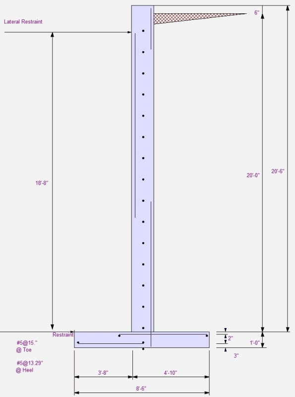
And on the compression-side bars since those are just for crack control, they wouldn't need those deep ldh embedments since they're not in tension, correct? We recently had a project where we had 5' wide x 12" thick footings for a wall such as this, but the contractor only poured the footings 10" thick instead of 12". We told them that was ok, so I brought up what is the point of 12" thick in the first place if 10" is ok. Thus all the discussion about rebar embedment. I have noticed in RetainPro when you have a pin-pin foundation wall that the rebar on the tension face is only shown at the area of maximum moment plus a little extension above and below. Please see below (ignore dimensions, rebar, etc.). I know this is just a rudimentary diagram provided by EnerCalc but it does seem to imply that the rebar embedment into the footing is not a major concern of the design.

I'd be very interested to hear anyone's opinions on the question of footing thickness, rebar embedment, etc. for a pin-pin design. Thanks!
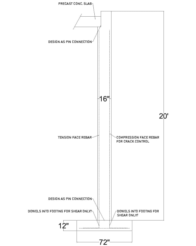
TALL_RESTRAINED_WALL_odeflz.jpg
ENERCALC_RESTRAINED_WALL_kmyubj.jpg
 
Replies continue below

Recommended for you

In my opinion, a 72" wide footing seems pretty wide to call it a pinned base. Although your idealized model says there is no moment at the base, the real structure doesn't care about your idealization and will behave according to the stiffness that your detailing provides. So in reality, there would need to be some amount of plastic behavior at the base in order to redistribute the moment to the middle of your "simply-supported" wall. I would probably just provide the 15" thick footing and call it a day rather than try to figure out the actual rotational spring stiffness of the footing. The KISS method of enveloping the design with the members designed for simple-support conditions and the connections designed for fixed-end conditions is often the easiest path.
 
If the basement slab is not rigidly connected to the foundation wall then the pin-pin assumption is valid, you can simply design the wall for the maximum moment (at somewhere below the mid-height) and add the required thickness for cover. Note don't forget to consider the potential hydrostatic pressure though, as the structure is not watertight.
 
Thank you OldDawg and le99.

le99, do you have an opinion about the footing thickness itself? We don't usually attach the slab to the foundation wall so if the pin-pin design is valid then is the rebar embedment into the footing a major concern? When other engineers in our area are going with 10" thick footings I'd like to feel confident doing that same thing or have a solid justification for making it thicker.
 
The depth of the footing equals l_dh (for hooked bars in tension) plus clear cover for direct contact with soil.
 
Well that was my question originally. With a pin-pin condition these bars won't be in tension as they aren't imparting any moment to the footing. As you mentioned, the maximum moment will be slightly below the mid-height but at the base the moment is zero. If the bars embed into the footing then it is creating a quasi-fixed condition as OldDawg alluded to. A related question is why does EnerCalc show the tension rebar at the center of the wall but then cut off after lapping with the compression bars on the top and bottom?
 
SarBear said:
Since this is a pin-pin wall these bars aren't transferring a moment into the footing, correct? The biggest bending moment from soil lateral load will be at the center height of the wall and then will be 0 at the top restraint and the stem/footing junction, so do these bars need to extend into the footing at all? I'd think they should extend into the footing to help with shear loads at the stem/footing interface, but is that necessary?

You may call it a pin connection, but the bars don't know that; they will resist moment until they fail in bond, after which they have little shear resistance.

When bars are adequately developed between wall and footing, a compression block is developed at the base of the wall on one side of the wall which helps to resist shear between wall and footing. If a pin connection develops, the shear resistance is largely lost.

The second detail has lateral restraint applied to the top left of the footing, but not to the wall itself, so shear resistance between wall and footing is absent. The vertical wall steel is not consistent with a pin-pin assumption. The bottom footing bars on the left should extend far enough beyond the left face of wall to develop yield.

BA
 
SarBear said:
Well that was my question originally. With a pin-pin condition these bars won't be in tension as they aren't imparting any moment to the footing.
You wrote that while I was writing my last comment.

It is important to note that the bars will be in tension and will impart moment to the footing to a limited extent. Dowels to the footing, if not adequately anchored, will be unable to resist shear after they have failed in bond.

Check shear friction requirements in the code.

BA
 
BAretired said:
The second detail has lateral restraint applied to the top left of the footing, but not to the wall itself, so shear resistance between wall and footing is absent. The vertical wall steel is not consistent with a pin-pin assumption. The bottom footing bars on the left should extend far enough beyond the left face of wall to develop yield.

That detail is just the "sketch" that EnerCalc provides when you're designing a RC wall. In reality we would have a 6" thick slab on top of the footing that butts into the bottom of the wall. When you say that the vertical wall steel is not consistent with a pin-pin assumption do you mean that it should extend all the way to the top and the bottom of the wall? Because that's what I would think which is why I'm asking why this program that probably thousand of engineers use does not show the rebar correctly, at least in my opinion.
 
I have never used EnerCalc and have no opinion on it at this time.

BA
 
There are two concerns about not to reinforce in accordance with standard hooks:

1. Relative rotation between the footing pad and the wall will introduce tension on one face of the wall, if there is not enough reinforcement to restrict the tendency of being pull-out due to rotation, the other face will be subjected to excessive compression.

2. Even 1 above is not convincing enough, what is the required development length for bars in compression? According to ACI 318-14 24.9.9.2(b), the minimum l_dc = 8", assuming the reduction factors in 24.9.9.3 are not applicable. This result isn't any better than providing the standard hooks (l_gh min = 6"), and providing there exists the risk stated in 1 above.

Make sense?
 
SarBear said:
A related question is why does EnerCalc show the tension rebar at the center of the wall but then cut off after lapping with the compression bars on the top and bottom?
It doesn't. It is showing tension bars only, not compression bars. The tension bars are at the inside face in the positive moment region and at the outside face in the negative moment regions. The fact that it is showing tension bars at the base should tell you that a pin connection assumption is not consistent with how the bars are being detailed.

SarBear said:
When you say that the vertical wall steel is not consistent with a pin-pin assumption do you mean that it should extend all the way to the top and the bottom of the wall? Because that's what I would think which is why I'm asking why this program that probably thousand of engineers use does not show the rebar correctly, at least in my opinion.
No. I agree with BA that the rebar detailing in your first sketch is not consistent with a pin connection assumption. It will resist moment whether you want it to or not. The program is showing the tension bars just fine, just not showing the extent of all the bars in the wall as most engineers would detail them for a practical, buildable design.
 
@le99,

1. I disagree. The compression face will receive maximum compression stress when the tension dowels are fully developed. Excessive compression stress is not the issue.

2. Compression bars do not need to develop anchorage. The concrete can develop enough compression by itself, with or without adequate tension bar anchorage.

It is not clear to me why a pin-pin support is being attempted. The wall and footing should be rigidly tied together to resist whatever moment exists at their junction.

BA
 
le99,

I can't find any of those code references you've provided for ACI 318-14. I'm guessing you're looking at a different edition. In my ACI 318-14 the development of compression bars is found in 25.4.9.1.

In any case, what I'm hearing is that if we've got #6 bars in the tension face then our embedment depth should be a minimum of 11.5" (using the cover modification factor of .7, otherwise it should be about 16.5"). I guess we could also use the As_required/As_provided ratio from ACI 318-14 25.4.10 to reduce the embedment depth.
 
OldDawgNewTricks said:
It is showing tension bars only, not compression bars. The tension bars are at the inside face in the positive moment region and at the outside face in the negative moment regions. The fact that it is showing tension bars at the base should tell you that a pin connection assumption is not consistent with how the bars are being detailed.
I don't want to get too far into the weeds with whether the program is doing things right or not, but the sketch I posted is definitely a pin design as there is a button saying "Stem Base Fixed to Footing" which I have unchecked.

BAretired said:
It is not clear to me why a pin-pin support is being attempted.
Per the other engineers in my office it's so that the footing can be designed for gravity loads only, while the stem is designed for the lateral loads from the soil.
 
Yes, you are correct on ACI reference (I was reading while made mistake in writing :). But at least now you recognize what the minimum depth of the footing pad is required. Note, a pinned connection needs to be able to transfer shear across the plane through shear friction, thus it is imperative to develop the wall bars into the footing pad.
 
SarBear said:
I don't want to get too far into the weeds with whether the program is doing things right or not, but the sketch I posted is definitely a pin design as there is a button saying "Stem Base Fixed to Footing" which I have unchecked.
You don't need to get into the weeds to prove it to us in this forum. But you definitely do need to get into the weeds to prove it to yourself. It is incumbent upon all engineers to verify that the software they use is correct and that you understand the results. It should be easy enough to do a hand calc with pinned supports to see if you get the same results. I'm just saying that the rebar locations that are shown in the sketch do not look like a pinned end analysis to me.

SarBear said:
Per the other engineers in my office it's so that the footing can be designed for gravity loads only, while the stem is designed for the lateral loads from the soil.
That is fine in concept. But if you provide details that resist moments but then neglect to design for those moments because they are not convenient, you may be violating section 6.6.5 which sets limits on the amount of moment redistribution that is allowed. Might need to think harder about how to detail the structure to match your assumptions.
 
Try the rules for slabs supported by edge beams - similar situation turned on its side. You could also use smaller starter bars lapped with the main reinforcement to improve development.
 
OP said:
Per the other engineers in my office it's so that the footing can be designed for gravity loads only, while the stem is designed for the lateral loads from the soil.
Creating a pin in a concrete member is not easily done. I don't recall ever attempting it, but I now understand the reason for it. The sketch below indicates a suggested method for creating a connection approaching a pin end. Red bars are tension steel. Green bars are nominal temperature steel. Black bars are footing reinforcement.

Tension reinforcement needs to be anchored to the footing to provide sufficient shear friction to resist the horizontal shear from the applied soil pressure. Temperature reinforcement (green bars) should not extend into the footing if moment transfer is to be avoided.

Restraint at the left end of the footing is better placed at the bottom of the wall, but the location shown is consistent with the OP's second diagram. If a slab exists at the base of the wall, it would be better able to provide restraint than passive soil pressure on the footing.

Capture_hnnxbs.gif


BA
 
I have never tried to create a pinned connection in cast-in-place concrete basement walls either. If for some reason I had to, I imagine that it would end up looking a lot like a precast or tilt-up wall panel connection. And I would pay extra attention to waterstopping and waterproofing due to the additional rotation that will occur. But if given a choice, I would just use standard details and design for the moment that will occur in real life rather than trying to explain to the contractor why he needs to build some unusual custom detail just so it can match an idealized analysis assumption.
 
Status
Not open for further replies.

Part and Inventory Search

Sponsor