Continue to Site

Eng-Tips is the largest engineering community on the Internet

Intelligent Work Forums for Engineering Professionals

  • Congratulations SSS148 on being selected by the Eng-Tips community for having the most helpful posts in the forums last week. Way to Go!

20' Tall Pin-Pin Foundation Wall

Status
Not open for further replies.

SarBear

Structural
Mar 14, 2022
38
Fellow Engineers,

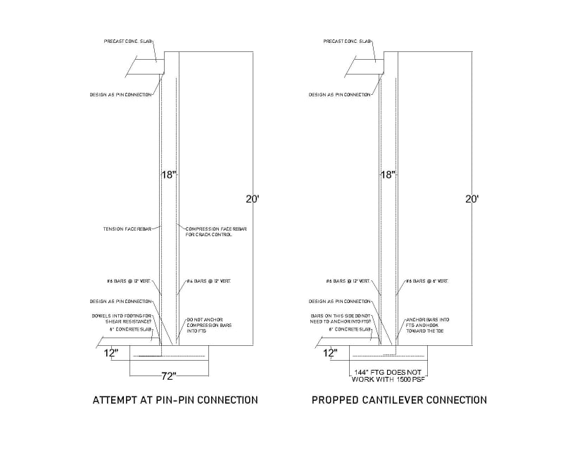
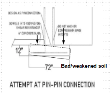
A discussion in our office lately has been about tall restrained pin-pin foundation walls. We've had quite a few residential projects come in lately where they have tall rooms underneath garages (15' tall theater room, 20' tall sports court, etc.). The discussion originally started because of a disagreement about how thick the footings for these type of walls should be. We've normally had these footings for super tall restrained walls be 12" thick, but the question of why 10" wouldn't work has been brought up. The loads coming down from the roof above, the weight of the concrete slabs in the garage, and the fnd wall itself are not such that there would be a shear issue with a 10" thick footing.

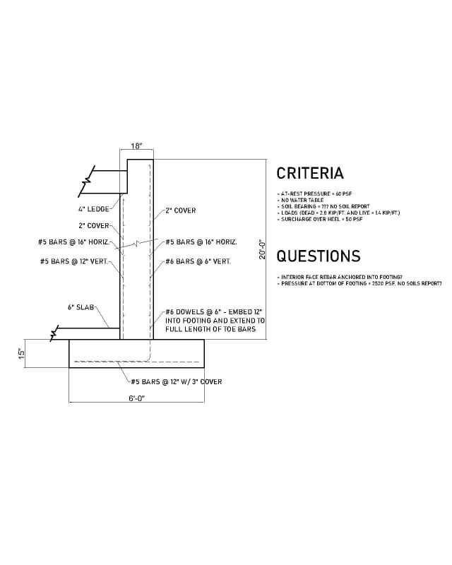
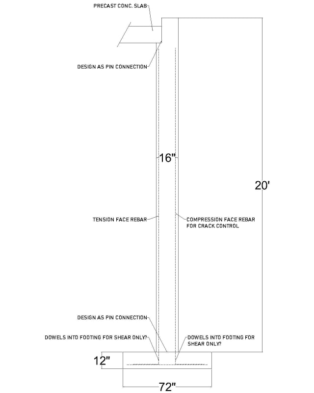
But what about rebar embedment from the wall above? These walls often have #6 or #7 bars on the tension face. For a #6 bar the ldh for hooked dowels into the footing should be around 12", so I'd think the footing should actually be around 15" thick for the ldh plus 3" cover. But that ldh is for hooked bars in tension. Since this is a pin-pin wall these bars aren't transferring a moment into the footing, correct? The biggest bending moment from soil lateral load will be at the center height of the wall and then will be 0 at the top restraint and the stem/footing junction, so do these bars need to extend into the footing at all? I'd think they should extend into the footing to help with shear loads at the stem/footing interface, but is that necessary?

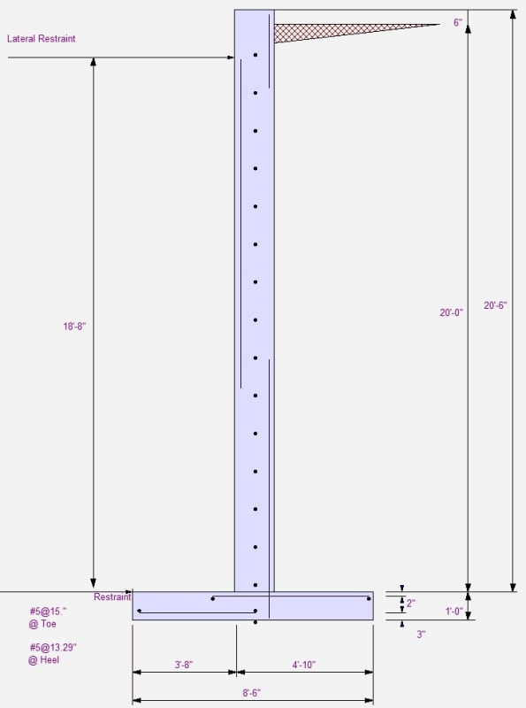
And on the compression-side bars since those are just for crack control, they wouldn't need those deep ldh embedments since they're not in tension, correct? We recently had a project where we had 5' wide x 12" thick footings for a wall such as this, but the contractor only poured the footings 10" thick instead of 12". We told them that was ok, so I brought up what is the point of 12" thick in the first place if 10" is ok. Thus all the discussion about rebar embedment. I have noticed in RetainPro when you have a pin-pin foundation wall that the rebar on the tension face is only shown at the area of maximum moment plus a little extension above and below. Please see below (ignore dimensions, rebar, etc.). I know this is just a rudimentary diagram provided by EnerCalc but it does seem to imply that the rebar embedment into the footing is not a major concern of the design.

I'd be very interested to hear anyone's opinions on the question of footing thickness, rebar embedment, etc. for a pin-pin design. Thanks!

TALL_RESTRAINED_WALL_odeflz.jpg
ENERCALC_RESTRAINED_WALL_kmyubj.jpg
 
Replies continue below

Recommended for you

Thank you all for your commentary. I wish the engineers where I work knew half as much as you guys.

I have attached an updated drawing showing some of the more realistic dimensions and reinforcement that I'm coming up with for pin-pin vs fixed conditions. OldDawg said earlier that my first sketch did not reflect a pin-pin condition and I can't figure out why. I have drawn the slab in its actual location on the updated sketch. One reason for trying pin-pin is to have the rebar in the wall be more reasonable. In that case I can get #6 bars on one face of the wall, but with a fixed base I'd need #6 bars in both faces because the moment changes sides of the wall.

Also, with a soil bearing pressure of 1500 psf I can't even get a 12' wide footing to work for the fixed condition. Do you see anything on my sketches that don't look right to you? I want to understand this because these type of walls come up more and more all the time but unfortunately the answers I've got from the higher-ups here don't make any sense to me (sounds like they don't make sense you to all either).

BAretired said:
Tension reinforcement needs to be anchored to the footing to provide sufficient shear friction to resist the horizontal shear from the applied soil pressure
Is that the only reason you see for anchoring it? If it's anchored then wouldn't it put some moment into the footing? The whole reason this question came up was a discussion about how thick the footing should be. I don't see why a footing thicker than 10" would be needed if we're not worried about ldh into the footing.

TALL_FND_nolc9w.jpg
 
A few questions on the design:

1) Footing pressure (factored).
2) Surcharge load on the backfill side.
3) Soil density, and lateral load coefficient.
4) Groundwater elevation, if present.
5) What is the development length for the bar extended into the footing pad (straight and hook), and what is the justification?

Also, how do you address the potential of footing pad rotation? (Note the rotation of the wall is not shown in the sketch below)

Untitled_lbpfxq.png
 
SarBear,
The design problem you are addressing is by no means simple. It requires careful thought, a rough idea of the magnitude of the axial load, height of backfill and soil properties. The detail I suggested earlier does not provide an ideal pin connection, but I hoped it might stimulate some discussion on E-T. It is not the first time this issue has come up. The following was a discussion fifteen years ago which makes for interesting reading:

thread507-198746

Additional articles are available on Eng-Tips and elsewhere. It is always a good idea to do a literature search before coming to firm conclusions.

BA
 
OldDawg said earlier that my first sketch did not reflect a pin-pin condition and I can't figure out why.
This was in reference to the second image in your first post, shaded purple. The reinforcement changing sides within the wall, and being on top on one side of the footing, really does suggest that there is a bending moment being transferred from wall to footing rather than a pin connection. You did say that you selected the pin option, but you should also check the bending moment diagram to see that it is being done by the software.

One reason for trying pin-pin is to have the rebar in the wall be more reasonable. In that case I can get #6 bars on one face of the wall, but with a fixed base I'd need #6 bars in both faces because the moment changes sides of the wall.
That should be accompanied by a reduction in the bending moment on the inside face. But yes, you need tension reinforcement on both faces for the fixed case, at least over part of the wall height.

Also, with a soil bearing pressure of 1500 psf I can't even get a 12' wide footing to work for the fixed condition. Do you see anything on my sketches that don't look right to you?
Hard to say without knowing the loads and what you're including in the bearing calc, but you did say that the wall load is fairly small which is why you're looking at a shallower footing. A guess: 20' * 80~100pcf = 1600~2000 psf pressure from just the overburden. The more you widen the footing, the more it approaches a simple case of footing loaded on one half (ie wall load becomes negligible), and 1600~2000 > 1500...
 
Like many others have said, these walls are a bit trickey and require careful consideration and detailing. Just looking at the image makes me feel a bit akward seeing a 16" wall founded on a 10" footing. Using enercalc you can 'Pin' the base like you have mentioned with a checkbox. But it is unlikely that you will be able to justify the detailing that it is a Pin (there is a reason that even after you tell Enercalc to Pin the bottom it still has you put a mat of rebar on the tension face....)

What about considering how construction phasing might impact this detail as well? If they backfill before both the SOG and the Upper level floor restraints are fully engaged, then you have a condition where you need flexural reinforcement on the backside. Typically I run these walls in at least two phases. One as a cantilever with backfill no other surcharges, and then another case for the final condition. Obviously if you know there will be shoring and proper construction phasing to ensure that only the ladder condition is applicable then you might skip that, but in my experience contractors rarely follow guidance from the EOR on this topic. I have seen many so called propped walls act as full unrestrained cantilevers with backfill loading.

It is not uncommon to see footings with a width around 1/2 the retained height when using 1500 psf. Especially with large loads coming from axial forces in the wall which is common for this type of support condition.

I am a bit curious on the model's loading though because I recently did a propped wall with significant vertical forces on it and was able to get a much less wide footing, albeit I chose a thicker footing and opted to fix the base of the wall to avoid this detailing solution. In my experience a little bit of mud doesn't rattle anyone's cages too much and I don't mess around when it comes to footings so I can sleep better at night.

I would fix the base, use the reduced hooked embedment provision, provide the thickness and steel you need and rest easy. Detailing that joint for a pin is almost definitely bound to cause water infiltration problems at best.


DriftLimiter said:
If they backfill before both the SOG and the Upper level floor restraints are fully engaged, then you have a condition where you need flexural reinforcement on the backside
That would add significant cost to project. The footing would be huge for a 20 ft. wall.
Seems it would be better to specify the sequencing rather than to design for worst case.
 
@XR250 You're right for such a tall wall I doubt the builders will have any problem following EOR direction to shore it up properly. Still the notion is worth considering when we specify these propped walls, I also think about this when I use slab on grade for sliding resistance.
 
driftLimiter said:
...use the reduced hooked embedment provision...
ACI 318-19 I believe lists standard hooks as one of the exceptions where the As,required/As,provided reduction is not applicable. There is the additional argument that if the bars are used for shear friction then they are required to fully develop Fy on each side of the joint so under older provisions As,required/As,provided = 1 for shear friction reinforcement.

I'm making a thing: (It's no Kootware and it will probably break but it's alive!)
 
Celt83 said:
ACI 318-19 I believe lists standard hooks as one of the exceptions where the As,required/As,provided reduction is not applicable
Indeed. That's not in 318-14 but it is there in 318-19.

Here is a more polished version of the wall with a fixed base, still a work in progress. I have noted some of the design criteria used and some questions as well. I don't know what to do about the footing width since I don't have a soils report. With this design the bearing pressure is a uniform 2520 psf at the bottom of the footing. Without a soils report I think I'd need to assume an allowable pressure of 1500 psf which I can't achieve until I have a toe of 7' and a heel of 4', making an 11' wide footing. Our firm and all the other local engineers would typically specify a footing in the range of 5'-7' wide on something like this. Should I quit my job and work somewhere where they know what they're doing? I really appreciate everyone's help. I am one who feels the need to understand everything and follow the code strictly so this particular engineering challenge is giving me ulcers.
TALL_WALL_UPDATED_chnml0.jpg
 
driftlimiter said:
I also think about this when i use slab on grade for sliding resistance.
That certainly could be an issue with 20 ft of backfill.
 
SarBear said:
Without a soils report I think I'd need to assume an allowable pressure of 1500 psf which I can't achieve until I have a toe of 7' and a heel of 4', making an 11' wide footing.

So get a soil report.

BA
 
I did a quick check on your design based on the assumptions:

Pin-Pin wall L = 18'-8", fc' = 4 ksi, fy = 60 ksi, d = 16" (int face)
Soil wt = 120 pcf, ko = 0.5 (non-yielding wall)

The resulting factored (1.4) Mu = 34 k-ft, available Mn = 24 k-ft (for #5@12" before reduction)
The reinforcing ratio is 0.0016 < 200/fy. Note your wall is a flexural element as opposed to the concentrically loaded wall, so the reinforcing ratio is questionable.

I could have made mistake in my quick evaluation, but please do double-check your design.
 
BAretired said:
So get a soil report
If only it were that simple. No one around here requires a soils report so if we start doing that then we'll be out of business.

le99 said:
I did a quick check on your design based on the assumptions
That last sketch I posted is for a propped cantilever design. From what you all are saying, it sounds like trying to do a pin-pin design is a fool's errand so I'm moving away from that.
 
If you were able to get a 6 foot wide footing to work without considering moment at the base of the wall, then it is apparent that you are using the presumptive 1,500 psf value as an allowable net increase in bearing pressure at the bottom of footing elevation without considering the 20 feet of overburden over the heel. Steveh49 alluded to this several posts ago and the presumptive load-bearing values section of the IBC also addresses this.

That being the case, my back-of-the-envelope calcs show that you should be able to make an 8 foot wide footing work when you include the base moment and all of the various loads applied at their respective eccentricities, including the counterbalancing effect of the overburden soil. This is based on an effective allowable bearing value of 1500psf + overburden. Whether this effective allowable bearing value at the bottom of your excavation is valid or not is typically a question for your geotechnical engineer. I have gotten different responses to this question from different geotechs, depending upon the particulars of the project, cut/fill, etc. But since you do not have a soils report, I suppose you will have to make that call.
 
Ok. While moment demand is reduced, but, how about the reinforcing ratio? Also, similar to beams, the positive bars need to be developed into support to be effective. Note, now the bars are subjected to tension as well, which can't be terminated at the face of support.

Untitled_svl8am.png
 
le99 said:
Sorry to say it simply wouldn't work. Do you have a senior engineer in the office who can help to check the design?
I'm not sure how many variations of "I'm beginning to suspect that all the engineers in my office don't know what they're doing" I need to say for people to understand. What I've been describing with the pin-pin design is what our firm does, it's what the senior engineers do, and it's what they've taught us to do. So now I'm asking them questions about it and they can't answer them to my satisfaction, they have nowhere they can point me to for further learning, and I'm trying to learn what I can from books I have sitting around, Google, and this forum. I have not been out of school very long at all, but they sure didn't teach us how to engineer a 20' tall wall like this in school. That would be fine if I had someone here in the office to teach me. Unfortunately, the "teachers" here in my office have no answers for me.

I really appreciate the help that you all are giving. I hope you can understand how you saying, "Sorry to say it simply wouldn't work. Do you have a senior engineer in the office who can help?" makes me feel even more lost. I know that no one here has any obligation to help me, but as a young engineer I'm just trying to find my way and do things how they should be done. So I'll say it again, hopefully as clearly as I can this time:

I want to know how to design a wall like this properly. School didn't teach me. The senior engineers at my company taught me, but as I'm asking them questions and researching things on my own I am finding that they don't know any more about this than I do. What you all are saying here is completely different from any discussion I've had with the senior engineers in my office. Any question I've asked them is met with a hand wave, a "they'll figure it out in the field", a "that's how everyone around here does it", or a "yeah the numbers don't work, but it will be fine." I've read every single thread about pinned foundation walls on this site multiple times, yet after all that reading I haven't seen anything resembling a consensus, I haven't seen anyone post a detail showing a finished design, and after hours of research I have not seen a single detail anywhere online or in a textbook for a scenario like this. I have only seen what the company I work for does, so I don't have the foggiest idea of what a robust design and detail for a 20' tall basement foundation wall should look like. Sorry, rant over. As you can tell, I am starting to get angry about my education and the "mentors" I currently have. I want so badly to be good at this, but I don't know where to turn for help.
 
@SarBear

I think many engineers sympathize with the feelings your having.

But I think your doing the right thing... you have done the research for yourself with the best resources you have available, you have followed the load path, considered the details and come up with a design. The best you can do is as you see fit. I think that this tension is much preferred to simply following along with what everyone has been doing in the past. You will learn much more deeply by questioning old designs.

Now if someone above you wants to do it another way and stamp it with their stamp then I guess your gonna have to live with that. Full-knowing you did your best to make it right from your standpoint is perhaps the best you can get in the current situation.


Many engineers have grown to have a solid understanding of engineering designs through trials and errors, luckily, most of us been benefitted from having good mentors to point out our mistakes, but not holding our hands to do our work.

This wall can be analyzed and designed as a simply supported beam between supports (the floors), or more conventionally, a propped cantilever. No matter which type of support system you are choosing, it always starts with a good analysis to obtain the reactions and internal forces required for the member design. At this stage, you need to assure the correct loads/loading pattern are used/applied. I do have concerns on this aspect though.

Once the member sizing and required reinforcement have been calculated, you have to make sure the reinforcement to be provided meets the minimum, or occasionally the maximum), reinforcing ratio specified by the code. Again, I have concerns about this aspect.

Now you are ready to figure out the details to connect the wall to its supports per the support condition assumed in the beginning, and figure out the required embedment, per code, to develop the required strength. Note that the member thickness often is controlled by this requirement.

The suggestions/comments above have pretty much summarized the entire design procedure, wish it helps.
 
SarBear said:
We've had quite a few residential projects come in lately where they have tall rooms underneath garages (15' tall theater room, 20' tall sports court, etc.).

If the floor area of the garage and tall room is not too large, you might consider using a mat foundation acting as a two way slab with all edges clamped. The sketch below assumes a two car garage with outer dimension 24'x24'. The overburden pressure is gone, reducing vertical load and the wall-slab moment reduces the midspan moment of the slab in both directions.

Capture_lyucdk.gif


BA
 
A typical residential basement wall is on the order of 8 to 10 feet tall, 8" thick with a single layer of reinforcement and will have a strip footing below it that is around 20" wide. The wall is usually designed as pinned at the bottom and pinned at the top. Different engineers may have different ways of explaining how/why the bottom behaves as a pin. I believe the self limiting rotation of the footing that is discussed in the thread referenced earlier by BAretired (thread507-198746) to be a realistic explanation. Essentially the footing is just an extension of the wall. If the lateral restraint is being provided by the friction between the bottom of the footing and the soil, that would be your point of support and the footing/wall interface would simply need to have enough rebar to develop the moment and shear at this "internal" location.

Your situation has a much wider footing than is typical in residential construction, which won't be as conducive to the rotation argument made above. That does not necessarily mean it isn't valid however. This is where engineering judgement is needed. If your rebar is detailed such that it can transfer a substantial amount of moment into the footing it will do that. Now the question is, where will that load go once it makes it into the footing? The footing will try to rotate, if the soil is strong enough to resist this rotation you will have a propped cantilever type situation. If the soil is not strong enough, it will "fail" at the toe and the footing will rotate to match the rotation at the bottom of the wall, just like with the narrow footing discussed above. No more issues.

Now say, the footing does provide plenty of moment resistance, causing the wall to try to act like a propped cantilever, however the reinforcing embedment in the footing can't handle this load so it fails. What will happen? The load will redistribute to act like the original pinned connection you designed for. The question you need to ask yourself is after this "failure", will the wall still perform as intended? Will there still be a safe way to transfer the shear? Will this small movement cause any issues to waterproofing?

Personally, I have no issue designing this wall as pin-pin, but if I were to have rebar hooks embedded in a "much wider than normal" footing on the outer face of the wall, I would prefer any "failure" to be through those bars yielding, not through a brittle concrete failure due to too small of an embedment length. Where as, if the foundation is narrow and I thought it likely the foundation itself would rotate before those bars fail, I wouldn't be too concerned about it.


Likely one of the bigger issues that hasn't been discussed here is the pinned assumption at the top. For a 20ft tall wall, it will take a substantial amount of anchorage and good detailing to ensure that shear can actually be transferred into the floor diaphragm (I'm assuming it's a traditional wood floor diaphragm).
 
Status
Not open for further replies.

Part and Inventory Search

Sponsor