SarBear
Structural
- Mar 14, 2022
- 38
Fellow Engineers,
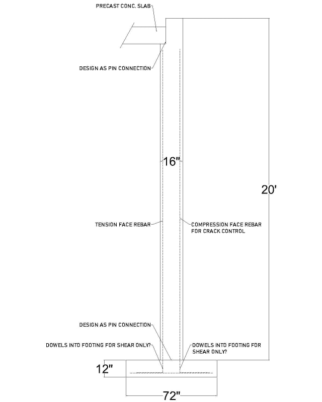
A discussion in our office lately has been about tall restrained pin-pin foundation walls. We've had quite a few residential projects come in lately where they have tall rooms underneath garages (15' tall theater room, 20' tall sports court, etc.). The discussion originally started because of a disagreement about how thick the footings for these type of walls should be. We've normally had these footings for super tall restrained walls be 12" thick, but the question of why 10" wouldn't work has been brought up. The loads coming down from the roof above, the weight of the concrete slabs in the garage, and the fnd wall itself are not such that there would be a shear issue with a 10" thick footing.
But what about rebar embedment from the wall above? These walls often have #6 or #7 bars on the tension face. For a #6 bar the ldh for hooked dowels into the footing should be around 12", so I'd think the footing should actually be around 15" thick for the ldh plus 3" cover. But that ldh is for hooked bars in tension. Since this is a pin-pin wall these bars aren't transferring a moment into the footing, correct? The biggest bending moment from soil lateral load will be at the center height of the wall and then will be 0 at the top restraint and the stem/footing junction, so do these bars need to extend into the footing at all? I'd think they should extend into the footing to help with shear loads at the stem/footing interface, but is that necessary?
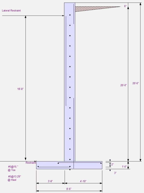
And on the compression-side bars since those are just for crack control, they wouldn't need those deep ldh embedments since they're not in tension, correct? We recently had a project where we had 5' wide x 12" thick footings for a wall such as this, but the contractor only poured the footings 10" thick instead of 12". We told them that was ok, so I brought up what is the point of 12" thick in the first place if 10" is ok. Thus all the discussion about rebar embedment. I have noticed in RetainPro when you have a pin-pin foundation wall that the rebar on the tension face is only shown at the area of maximum moment plus a little extension above and below. Please see below (ignore dimensions, rebar, etc.). I know this is just a rudimentary diagram provided by EnerCalc but it does seem to imply that the rebar embedment into the footing is not a major concern of the design.
I'd be very interested to hear anyone's opinions on the question of footing thickness, rebar embedment, etc. for a pin-pin design. Thanks!


