Continue to Site

Eng-Tips is the largest engineering community on the Internet

Intelligent Work Forums for Engineering Professionals

  • Congratulations KootK on being selected by the Eng-Tips community for having the most helpful posts in the forums last week. Way to Go!

24 MVA 125 rpm Hydro unit - Stator vibration at 104,2 Hz - why?

Status
Not open for further replies.

Jari T

Mechanical
Jul 27, 2023
5
Hi.

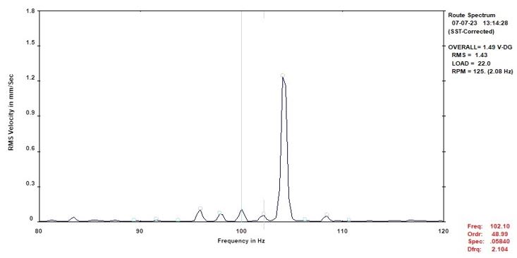
I measured a bit strange stator vibrations at one hydro power unit. It is a 125 rpm vertical Francis turbine (~24 m head) directly connected to the generator. There were totally four accelerometers installed radially at the stator frame and all measurement locations indicated similar responses. Typically it is the 2X line frequency (100 Hz) that jumps up when the unit is excited. (Typically means another similar units, this was the first measurement at this specific unit so so not know the history) Now the highest component was ~104,2 Hz meaning 100 Hz + 2X rotational frequency (see attached spectra). The grid is very stable so the frequency is not 2xLF. Any ideas what causes this?

Br:
-Jari
 
 https://files.engineering.com/getfile.aspx?folder=15465779-7e93-4ad9-9232-8d953376726f&file=Stator_vib_104,2_Hz.jpg
Replies continue below

Recommended for you

No idea . . . but does it matter? Plant operators, regardless of type, have routinely encountered this over the decades, and are not at all fazed by "hurry-through-the-critical speed" generating units.

CR

"As iron sharpens iron, so one person sharpens another." [Proverbs 27:17, NIV]
 
The file won't open for me. Perhaps edit the post to embed the image using camera icon?

Without seeing the chart, any chance it is 50 Hz electrical times 2.083 Hz mechanical rather than 2*50Hz electrical plus 2*2.083 Hz mechanical?
 
52.1 Hz prior to connecting to the grid is not uncommon.
It would be trimmed down a little before the breaker was closed.
If the unit is connected to the grid and showing that peak at 104.2 check the calibration of the equipment.
A quick test on equipment that is known to exhibit grid frequency vibration may be a quick way to verify the calibration.
It is hard to understand what may cause a vibration so close to the grid frequency, but not at the grid frequency.

My conclusions:
Either the unit was not connected to the grid when the measurements were taken,
or
The test instrument is about 4% out of calibration.
or The grid was running at 54.2 Hz that day.

The grid is very stable so the frequency....
That may be, but unless you have a true calibrated frequency meter online at all times,,,,,how would you know.
I have worked with a lot of small standby generators and with a small islanded power plant, actually on an island. About 2 MW capacity.
Without instruments, frequency swings are unnoticed by consumers.
Some UPS units will not track other than minute frequency swings, most do. I have only once found a small UPS that had issues when the frequency was 1 Hz out.

I have a hard time understanding how a condition causing vibration may advance 14.5 degrees every revolution.

--------------------
Ohm's law
Not just a good idea;
It's the LAW!
 
Thanks for answers!

Comments (sorry, first time here so can not use all fancy stuff what the page offers :))

to crshears: Probably it does not matter and have been there for a long time. Just want to know the reason for the excitation.

to bacon4life: Sorry, wont open for me either.
Stator_vib_104_2_Hz_2_cytrvu.jpg
tried now with the camera image. If it will not open, the picture just presents measured vibration response spectra having following rms- amplitudes: ~0,1 mm/s @95,84 Hz - ~0,1 mm/s @97,92 Hz - ~0,1 mm/s @100,0 Hz - 0,1 mm/s @102,8 Hz - ~1,25 mm/s @104,2 Hz. What comes to 104,2 Hz frequency there are of course lot of possibilities how it builds up. Just wanted to give a combination what matches the frequency. Actually your 50 times 2,08 Hz is more realistic and also 100 Hz with 2,08 Hz (rot. speed) sidebands are one potential theory. 100 Hz + 2*rot.freq was not a good example.

to waross: Vibration resposes was measured when the unit was excited and also when connected to the grid. The automation (automation, excitation, syncronization, protection etc.) was just modernized and I made measurements during commissioning. So all in that side is new and the most critical instruments have to be doubled. It is not often when you can say that you are 100% sure about something but in this case I can say that it is not problem with the instruments, especially when I was not responsible for the electrical part :) The unit is located in northern Europe and we have very stable grid. Such a big frequency deviation is impossible. When the unit was not synchorinized the generator frequency was 49,77-49,84 Hz and when synchronized 49,95-50,05 Hz. I know some of the problems with small units & weak grids and island mode operation but this case has nothing to do with those.
 
Not shown on the chart.
Do you have a vibration at 4.2Hz?
Salient poles?
Possibly the air gap of one pole off spec?
One coil reverse connected?


--------------------
Ohm's law
Not just a good idea;
It's the LAW!
 
Please disregard my earlier post; from the follow-on thread it has become clear I completely misunderstood what was being asked.

CR

"As iron sharpens iron, so one person sharpens another." [Proverbs 27:17, NIV]
 
Rotor ground fault or turn-turn fault? Jumpered coil is equivalent to a turn-turn fault. But it really would show up at the mechanical frequency.

I’ll see your silver lining and raise you two black clouds. - Protection Operations
 
Just curious, how many wicket gates and turbine blades? Could you possibly be seeing prime mover vibrations coupled to the stator?

Just a thought.
 
If you are using accelerometer vibration probes, they are not reliable at speeds below 600 RPM. Normally, you measure contact/non-contact shaft displacement probes to measure the shaft movements for such slow speed machines. And 1.2 mm/sec rms is low and is in smooth range.

Muthu
 
Hello all. Comments & answers:

to waross:
- There is vibration at 4,2 Hz frequency. Amplitude is 0,13 mm/s, rms and measured at the stator core.
- Saliet poles = yes
- Air gap issue = fully possible. Probably the air gap is not measured for a loooong time (=meaning a few decades)
- Reverse connection of one coil -> will lift up this possibility with the discussions

to davidbeach:
- Rotor ground fault = no. There are just installed a new system (which is tested and fuctioning) and no indication about the rotor-to-ground fault. Coil issues will be hopefully investigated.

to wcaseyharman:
- 24 wickets but do not know the number of turbine blades, have to check it. The phenomenon is clearly connected to the generator excitation.

to edison123:
- I measured both: relative shaft vibrations and absolute bearing/stator vibrations. I use low frequency accelerometers and those are reliable for 2 Hz (easily). Between 0,5-2 Hz the signal condition has an inmportant role and when you are doing that right the signal is relable at those frequencies too. In this case the question was raised regarding stator core vibrations in the region of 100 Hz. My opinion is that the properly chosen haccelerometer is the best sensor for a such measurements. What comes to the the absolute magnitude: 1,2 mm/s rms, you have that right. It is not a high amplitude. More or less typical. But the original question was about the highest frequency. Why not 100 Hz but 104,2 Hz?

Br:
-Jari


Why not 100 Hz but 104,2 Hz?
It's called a beat frequency.The sum of 100 Hz and 4.2 Hz.
Puzzling to me is why we are not seeing the difference eg a similar peak at 95.8 Hz.
We do have a peak at 95.8 Hz but the amplitude is much lower than what I would expect.

--------------------
Ohm's law
Not just a good idea;
It's the LAW!
 
I missed the fact that 4.2HZ is related to 2X rotational speed. I take it that this is a 48 pole generator?

Has a pole drop test or a flux test been performed to check for shorted turns on the rotor? As you know shorted turns on the rotor will create an unbalanced magnetic attraction that would cause vibration related to running speed that potentially would add to the 100HZ fundamental. Very similar to eccentricity in the air gap that was mentioned earlier.
 
to waross: I have learned term beating so that it is the penomenon where frequencies close to each other interact. Typical examples are belt driven fan where pulleys have close diameters and motor & fan have close rotation speeds - or - two machines with nearly same speed sitting in the foundation that allows vibration to travel between machines - or - 2 pole induction motor with an eccentric air gap -> 2*LF and 2*rotational speed are close each other due to slip. Sure there are lot of other exapmles but those are that I have measured quite a few. When close frequencies interact (beats) vibration amplitudes go up&down. If one frequency is 50 Hz and another 49,8 Hz then you have 5 seconds time between max&max and min&min. In this case the stator frame is showing stable amplitudes in a function of time. Based on that the phenomenon is not beating. (or I have understood term beating totally wrong). Just by looking the spectra it seems that there are sidebands what we see. But is the center frequency 2*LF (100 Hz) having rot.speed sidebands? If it is, why only 104,2 Hz jumps up like you wrote? I have seen unsymmetrical sidebands for example in stator current specktra of an induction motor which had failure in rotor cage (broken bars and some cracks in the end ring). It was long time ago so do not remember was it upper or lower sideband which was highest. However, sidebands are just quessing from my side. I cannot build a theory to support that.

to wcaseyharman: Yes, it is 48 pole generator. I do not know about the details regarding electrical measurements, have to ask.
 
Looking at the spectrum I would guess the overall pattern is 2*LF with multiple running speed sidebands. The fact that one sideband at 104.2hz happens to jump up higher than the others may simply be amplification by mechanical resonance at that particular frequency. If you can reproduce that frequency by bump testing various locations, that would tend to support the idea of resonant amplification. But if you can't reproduce it, that would not be as conclusive because recreating the spatial excitation pattern necessary to excite the unknown modeshape may not be a trivial excercize (especially in the case of relatively high resonant frequency on large structure where the structures act very flexible and modeshapes tend to be complicated... the opposite of simple rigid body motion)

The 2*LF with multiple running speed sidebands seems consistent with a rotating asymmmetry of some kind (as previously mentioned, possible shorted turn, possible rotating eccentricity). But if you confirm that one peak is resonantly amplified, it may not be as much a concern since the remainder of that pattern is quite low in magnitude.

Jari T said:
I have seen unsymmetrical sidebands for example in stator current specktra of an induction motor which had failure in rotor cage (broken bars and some cracks in the end ring). It was long time ago so do not remember was it upper or lower sideband which was highest. However, sidebands are just quessing from my side. I cannot build a theory to support that.

For induction motor, asymmetrical pole pass sidebands around 1x line frequency tend to be seen in the CURRENT spectrum when the motor is driving a high inertia load. To be more specific: For high inertia load as rotor bar degrades typically only one sideband goes up; while for low inertia load as rotor bar degrades typically they both go up at similar magnitudes. I have seen this behavior on the normal low-level sidebands of our motors (our motors which have a huge flywheel attached show normal sideband on only one side while our other motors without flywheel show equal normal sidebands on both sides). I have seen a theoretical explanation published to explain that type of behavior, but it's quite complicated. I'll post a link if I can find one, but I don't think it's relevant to your situation.
 
Pete said:
our motors which have a huge flywheel attached show normal sideband on only one side
I think that answers my question about the lack of a matching amplitude on the lower sideband.
Thanks.

--------------------
Ohm's law
Not just a good idea;
It's the LAW!
 
electricpete said:
I have seen a theoretical explanation published to explain that type of behavior, but it's quite complicated. I'll post a link if I can find one, but I don't think it's relevant to your situation.
The only link I can find is a paid article AI techniques in induction machines diagnosis including the speed ripple effect
I do have a copy of the article but it's copyrighted. In spite of AI in the title it's not just computer based, there's a lot of human-understandable stuff in there. My simplistic explanation (which is all I have, I don't understand a lot of the article) would be that the direct effect of broken rotor bar for motor under load at constant speed is the lower sideband. If inertial is low enough that the resulting torque oscillations cause speed oscillations, then these speed oscillations induce additional fields and currents which move part of the lower sideband to the upper sideband and the two sidebands tend to equalize. That is the speed ripple effect referred to in the title.
 
> I think that answers my question about the lack of a matching amplitude on the lower sideband.

My guess would still be resonance. There may be other explanations far beyond my understanding. I personally don't see the analogy between pole pass frequency sidebands around 1xLF in current on an induction motor and these 1x/2x turning frequency sidebands around 2LF vibration in a sync generator. But you never know...
 
Did you try just a bump test (nothing electrical going on)?
 
Looking around online I found a paper that ties stator vibration with 2*fe+-Fr for a rotor eccentricity (Fe is grid frequency, Fr is rotor frequency). Not quite the frequency you’re seeing but same idea. This paper references another one on the topic but I wasn’t able to open it.
At the next shutdown you might consider a pole drop test and an air gap measurement if you don’t have that data already.
 
Status
Not open for further replies.

Part and Inventory Search

Sponsor