I have a 350A neutral resistor for a 2MW generator, and I'm trying to determine size of neutral resistor cable. I used equation: (1/A)^2 *t = 0.0297*log[(T2-234)/(T1-234)], and came up with A=23,643 (t=10s, T2=150, T1=90). This means I can use #2 AWG cable. The phase conducts are 6-1/C #250 (2 conductors per phase). Does that seem correct?
Navigation
Install the app
How to install the app on iOS
Follow along with the video below to see how to install our site as a web app on your home screen.
Note: This feature may not be available in some browsers.
More options
You are using an out of date browser. It may not display this or other websites correctly.
You should upgrade or use an alternative browser.
You should upgrade or use an alternative browser.
2MW Generator Neutral resistor cable size
- Thread starter Mila2015
- Start date
- Status
- Not open for further replies.
You are overthinking it.
Use the ampacity tables in the code book.
Not just a good idea, it's the law.
My code book shows 250 MCM for 75C copper in a raceway or cable for 350 Amps.
My code book shows the ampacity of #2 AWG as 280 Amps, in free air, at the 200C rating.
My code book shows the ampacity of #2 AWG as 115 Amps, in raceway or cable at the 75C rating.
#2 AWG is just a little light.
Bill
--------------------
"Why not the best?"
Jimmy Carter
- Thread starter
- #3
waross, thanks for the reply. Well, this cable is to feed a neutral resistor used for low resistance grounding. The resistor is rated for 350 A, 10 sec. The generator is 4.16KV. The cable will only see current during a ground fault. I believe the NEC tables you were referring were for continuous rating correct?
The code that I work to, the Canadian Electrical Code, does not allow a reduction in the size of the neutral grounding resistor conductors based on a short time rating.
Check your local code for your local regulations.
On a side note, at 350 Amps, a single conductor must not be magnetically encircled.
Bill
--------------------
"Why not the best?"
Jimmy Carter
Check your local code for your local regulations.
On a side note, at 350 Amps, a single conductor must not be magnetically encircled.
Bill
--------------------
"Why not the best?"
Jimmy Carter
- Thread starter
- #5
You are correct! Based on NEC 250.36B, the grounded system conductor shall have ampacity >= resistor current rating, which is 350A. The question is, which table to use?! This would be single conductor, 5KV, insulated/shielded cable in underground PVC conduit. I think the closest table from NEC would be Table 310.60(C)(77)(Detail 1), but like all tables in NEC, this is for (3) conductors in electrical duct. Anyone know of more applicable table for this application?
This is the wording in the CEC:
For 350 Amps at 75C rating my table shows 250 kcmil cable.
Does that match your table value?
Bill
--------------------
"Why not the best?"
Jimmy Carter
Cross reference.CEC said:Table 2
Allowable ampacities for not more than three copper conductors,
rated not more than 5000 V and unshielded, in raceway or cable
For 350 Amps at 75C rating my table shows 250 kcmil cable.
Does that match your table value?
Bill
--------------------
"Why not the best?"
Jimmy Carter
For shielded cable as per CEC;
Bill
--------------------
"Why not the best?"
Jimmy Carter
Myself I would be guided by this and would as a first solution attempt to prevent the flow of sheath currents.CEC said:4-010 Induced voltages and currents in metal armour or sheaths of single-conductor
cables (see Appendix B)
(1) Where sheath currents in single-conductor cables having continuous sheaths of lead, aluminum, stainless
steel, or copper are likely to cause the insulation of the conductors to be subjected to temperatures in
excess of the insulation ratings, the cables shall be
(a) derated to 70% of the current-carrying rating that would otherwise apply;
(b) derated in accordance with the manufacturer’s recommendations and in compliance with
Rule 2-030; or
(c) installed in a manner that prevents the flow of sheath currents.
Bill
--------------------
"Why not the best?"
Jimmy Carter
- Thread starter
- #8
Thanks wross! This section from NEC I'm looking at looks like this:
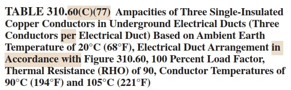
For 250 MCM (90 degree C),2001-5000v, single duct, the ampacity is 320A corrected to . I may have to use 2-1/C #250, since that's what I'm using for the phase conductors.
With regards to shield, this is what it says:
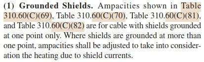
So, this only applies to "Insulated single conductor isolated in air", and "single insulated conductor directly buried in earth" for some reason!
For 250 MCM (90 degree C),2001-5000v, single duct, the ampacity is 320A corrected to . I may have to use 2-1/C #250, since that's what I'm using for the phase conductors.
With regards to shield, this is what it says:
So, this only applies to "Insulated single conductor isolated in air", and "single insulated conductor directly buried in earth" for some reason!
Shield current resulting from grounding at more than one point adds heat to the cable no matter what the installation method.
Is your conduit direct buried?
Using two parallel cables you can probably go less than 250 kcmil.
As I mentioned before, beware of magnetic encirclement, not only in conduit but when exiting enclosures.
The CEC considers magnetic encirclement to be an issue at current over 200 Amps.
Bill
--------------------
"Why not the best?"
Jimmy Carter
I don't have a current copy of the NEC.
I can only give suggestions and general guidance based on the similar but not identical CEC.
Anyone with direct NEC experience is welcome to jump in and take over here.
Bill
--------------------
"Why not the best?"
Jimmy Carter
I can only give suggestions and general guidance based on the similar but not identical CEC.
Anyone with direct NEC experience is welcome to jump in and take over here.
Bill
--------------------
"Why not the best?"
Jimmy Carter
Calculated as per IEC 60287 the single core 5 kV 1/0 awg copper conductor shielded cable it will withstand short-circuit for 10 sec., in case that the resistor will be short-circuited [my appreciation 2.7 kA] , but not the continuous load of 350 A. Skin effect is low and proximity does not exist but the shield losses can be 20%[20% overlapped tapes].So the current for xlpe or epr insulation 90oC it is only 300 A .If you intend to install a cable to sustain a continuous load of 350 A in a concreted pvc duct you need a 2/0 awg copper xlpe/epr insulated.
For 10 seconds at 350 A [See IEEE 242-2001 pages 312 to 318] 1/0 awg [if it worked continuous at 300 A before]![[blush]](/data/assets/smilies/blush.gif "[blush] [blush]") will reach only 95oC after 10 seconds.
will reach only 95oC after 10 seconds.
For 10 seconds at 350 A [See IEEE 242-2001 pages 312 to 318] 1/0 awg [if it worked continuous at 300 A before]
will reach only 95oC after 10 seconds.For what it is worth: The CEC refers to neutral grounding devices.
For a current greater than 10 Amps (low impedance grounding) provisions must be made to disconnect the system in the event of a ground fault.
The system grounding device need not be continuous rated.
There is no provision to reduce the size of the conductor or to use a short time rating for the conductor.
Who owns the generator?
If this is a privately owned standby generator this code applies in Canada.
If a utility owns and operates the generator it may be exempt from these provisions.
Bill
--------------------
"Why not the best?"
Jimmy Carter
For a current greater than 10 Amps (low impedance grounding) provisions must be made to disconnect the system in the event of a ground fault.
The system grounding device need not be continuous rated.
There is no provision to reduce the size of the conductor or to use a short time rating for the conductor.
Who owns the generator?
If this is a privately owned standby generator this code applies in Canada.
If a utility owns and operates the generator it may be exempt from these provisions.
CEC said:exceptions:
(a) installations or equipment employed by an electric, communication, or community antenna distribution
system utility in the exercise of its function as a utility,
Bill
--------------------
"Why not the best?"
Jimmy Carter
By the way, the short-circuit formula according to NEC Table 240.92(B) Tap Conductor Short-Circuit Current Ratings is different than the formula on o.p. and has to be:
(I^ 2/A^ 2).t = 0.0297 log10 [(T 2 + 234)/(T 1 + 234)]
where T2=250oC[EPR] and T1=To=20oC [earth temperature as per NEC 310.60]
(I^ 2/A^ 2).t = 0.0297 log10 [(T 2 + 234)/(T 1 + 234)]
where T2=250oC[EPR] and T1=To=20oC [earth temperature as per NEC 310.60]
- Thread starter
- #16
It seems like I was referring to the wrong NEC section, as 250.36 maybe for systems <=1000v. For applications >1000v, "250.187 Impedance Grounded Neutral Systems" applies. However, sizing requirement for the Neutral conductor in this section is not clear. It reference sizing of "Grounded Conductor" to be based on table 250.102C(1), but is "Grounded Conductor" the conductor from Neutral point to the resistor, or is it the conductor from ground side of resistor to generator breaker?
For my application (4160v, 2000KW generator, 350A resistor, 6-1/C #250 ungrounded conductors):
1- Per table 250.102C(1) I need to use a minimum of 1/0 grounded conductor (again, this might not be the neutral conductor!)
2- Per equation "(I^ 2/A^ 2).t = 0.0297 log10 [(T 2 + 234)/(T 1 + 234)]" which take into consideration the insulation material (which applies to a neutral conductor), the size (assuming 10 sec) would be = #8AWG (assuming EPR insulation). I would use the MV #250 MCM cable since that's what's used for non-grounded conductors.
I'm still not sure of Code's sizing requirement as it is not detailed in section 250.187 as I stated.
- Status
- Not open for further replies.
Similar threads
- Replies
- 7
- Views
- 14
- Question
- Replies
- 9
- Views
- 49
- Question
- Replies
- 6
- Views
- 33
- Replies
- 7
- Views
- 26
- Locked
- Question
- Replies
- 8
- Views
- 16