Hello,
We have an installation with the following configuration,
Connection to the grid with a Y-Y Stepdown Transformer 750 KVA, from 12470/7200 to 480/277V, 60 Hz.
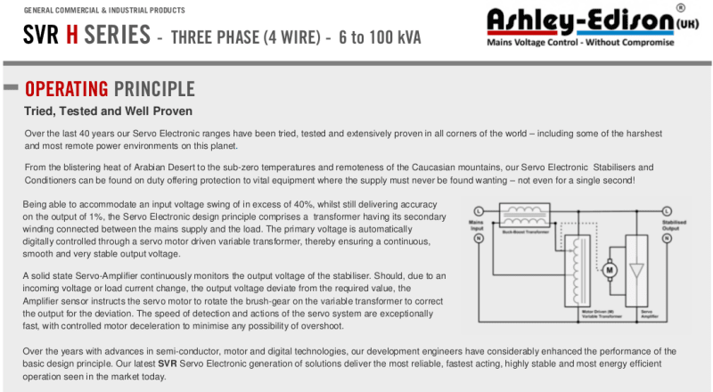
The load are 3 phase air conditioners, the compressors are connected in Delta, the current of consumption is around 25 Amps, each, we have normally 02 runnings, and 01 in stand by, like there are voltage fluctuations from 410 V to 550 V, we have installed one new 3 phase Voltage Stabilizer type Servo, internal arrangement type Y with neutral.
We have the following situation, when the compressors are running at least one, with 20 Amps, the stabilizer is working fine, when the compressor stopped(minimal current in the load around 1 Amp), the stabilizer starts with erratic comportment, noise in the internal transformer, one of the arms of the servo going to full movement and the equipment is tripped for high current in one phase, it just only happens with no load.
My Hypothesis are:
- The neutral in the inlet transformer does not have a good reference with earth, and we do not have a good reference with no load, the neutral is causing the unbalance in the equipment.
- Some problems of earth.
- We are thinking install one small 3 phase load (5 Amps) to cause that the stabilizer has all-time one triphasic load.
Please any advice or experience is really appreciated
Regards,
Mario JGG

