Continue to Site

Eng-Tips is the largest engineering community on the Internet

Intelligent Work Forums for Engineering Professionals

  • Congratulations KootK on being selected by the Eng-Tips community for having the most helpful posts in the forums last week. Way to Go!

3-story porch (wood frame)

Status
Not open for further replies.

Ben29

Structural
Aug 7, 2014
318
I specified this porch to have continuous 6x6 wood posts with wood beams framing into the sides of the wood post via simpson face-mount hangers. The contractor wants to splice the wood post at the second level. I have never done this before.

He suggested butting the ends of the post together and splicing it with a 24" long, L5x5x5/16 angle bolted to the post. See images below. He provided the sketch of the splice.

He doesn't want to use steel due to cost. He said he could find the long 6x6 post that I specified (they are $2000 per post he said).
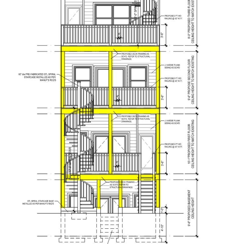
3_story_deck_nejbtj.png

splice_aqk2iw.png
 
Replies continue below

Recommended for you

What's the intended lateral system? I don't see why it couldn't be spliced provided you have a competent diaphragm and lateral system.
 
No. That's a terrible idea. You don't splice a post at a beam connection like that.

I'd do individual posts for each level. Pay close attention to the detailing at each floor, and provide lateral restraint tied back to the primary diaphragm. Design the deck as a subdiaphragm (NDS has plank diaphragm capacities). If they're using composite, then do diagonal bracing on the underside.

You don't run posts full height through the building, do you? No need to do it here, either.

If you really want them to be full height, search on here. I posted a link to a guide from the City of Chicago I used to have that includes a splice detail for this sort of situation. Not sure where it is now, but I know that thread is still floating around. Though steel would be better.

 
jayrod - end distance in the main member for fasteners going into the top post won't be large enough, and so the capacity of the beam hanger will suffer.

You're likely to get a little restraint from the friction between the posts, but I don't think it would be enough to say that's not an end condition for connection design purposes.
 
Pharm: Is this the detail you are talking about?

CHI-TOWN_cnoace.png
 
I don't see a compelling reason why it has to be a continuous post. This is certainly a gravity only post. As long as it is reasonably tied into the lateral system, I think the posts could be split up.

The only issue I can imagine is if the porch gets significant lateral drift and P-Delta becomes a problem. In that case, a continuous column would be my preference. Though this is more a personal preference than a true requirement.

That being said, I'm not a fan of that splice detail. Why splice it at the floor location where the beam frames in? that would monkey with the beam hanger, right?
 
Looks familiar. I think they talked about distance from other connections, too.

For the record, I don't love that detail. It's a moment splice in a wood post, outside. But it's an example of what some people have done and what is, apparently, endorsed by at least one jurisdiction. Like I said - I break the posts at each level of the deck and design each floor as a cantilevered diaphragm. You need to do it for your third floor anyway - might as well do all three and make the deck framing simple.
 
Pharm: When you say, "pay close attention to the detailing at each floor," what do you mean, exactly?

I am providing deck tension ties, as required per code.

If you are posting up off of each level, how are you fastening the base of the post to the level below?

Are you bracing the top of each column via the wood knee-brace?
 
That's the detailing I'm talking about. I usually have the post above bear directly on the post below (or the beam if it's wide enough) with a joist on each side fastened to it. If the loads are extreme enough (not common on a deck) I might add some additional blocking and straps. Tie it to the post below with a steel strap for uplift resistance.

 
Why not just us a post cap and have the beam sit over the column? You could then have the column above terminate on top of the beam and use another post cap if you have room to fit, or H, A clips and straps to drag loads down. I assume there is a perimeter beam so a post cap (think Simpson CC or CCQ) would make it easy to attach everything in my opinion. For the lateral system, having the beams each end gives you a nice chord member that can drag into the floor framing/diaphrgam although you could also use a joists.
 
You can do a lot of things on paper but I actually prefer to have some nominal, lateral resistance out at the edge of the deck, even if that's a belt and suspenders addition to the cantilevered diaphragm stuff. I like knee braces and see some logic in the Chicago splicing setup.

OP said:
I am providing deck tension ties, as required per code.

Is your floor framing parallel to the wall or perpendicular to the wall behind the deck? In many parts of north America, conventional detailing can make it quite difficult to get the chords of the cantilevered deck diaphragm run properly into the main diaphragm.
 
Not related to the question, but there doesn't seem to be much of a lateral system at the rear exterior wall there. If you are cantilevering the deck laterally, I imagine that's where the force would need to go.
 
phamENG said:
jayrod - end distance in the main member for fasteners going into the top post won't be large enough, and so the capacity of the beam hanger will suffer.

I'm not sure that I buy that:

1) Perhaps the fasteners in the low post can deal with the beam shear on their own and/or;

2) Graphically, the lowest fastener in the upper member still looks to have roughly 8" of end distance. I didn't bother to check NDS but 16 bolt diameters sounds like a fairly generous end distance to me.

Granted, to get a faux moment connection ala Chicago, one would probably want to spread out the fasteners a bit more than the contractor's details shows.
 
jdg said:
If you are cantilevering the deck laterally, I imagine that's where the force would need to go.

True. Hopefully the balcony edge framing line doesn't need to be the lateral support for the main building. Damn infills...
 
KootK - Thanks for making me look closer. I was thinking the angle was flipped and they were using a beam hanger like what the OP had originally planned. Integrating both connections into a single weldment may be feasible.

As for the Chicago detail, note that it says "bolts required to resist buckling moment" and then gives a minimum. I know a lot of engineers who wouldn't know how to approach calculating a "buckling moment" for the purpose of designing that connection, so I'm pretty sure that's not intended for direct consumption by contractors (though I'm sure it is commonly copied and submitted as is).

KootK said:
In many parts of north America, conventional detailing can make it quite difficult to get the chords of the cantilevered deck diaphragm run properly into the main diaphragm.

Especially elevated decks if they aren't a primary access point to the structure. Most contractors in my area leave decks for last and build them like an afterthought. So there's lots of "how do we install that? we already have a ceiling in place" and "what do you mean it has to be flashed?" So there's certainly some value to providing additional bracing. The trouble is figuring out the design load for the bracing as it isn't codified anywhere. And you can't extrapolate it from the prescriptive lateral connection requirements as the effective lateral load that the code minimum can resist varies with deck size and aspect ratio. And the typical details for this are (often) laughably inadequate for most decks in custom homes.
 
The interior framing runs perpendicular to the deck joists. Here is my detail.

deck_seq4tq.png
 
Nice, that's solves the cantilevered diaphragm chord issue in my opinion.
 
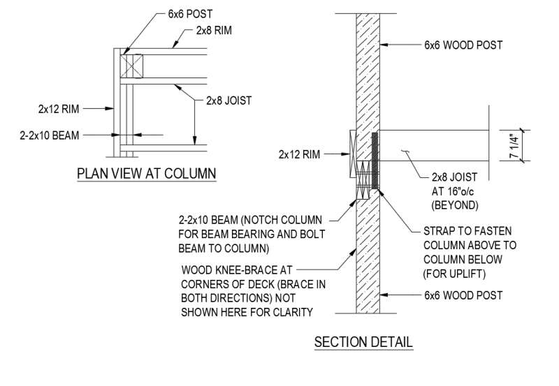
So you are telling me it is OK to post up from the column below? See below sketch. I will notch the top of the column to sit the beam on. I will bolt the beam to the column. Then I will post up off of the column. Tie it together with a simpson stap on either side. Then I lock it all in by fastening the rim board and floor joist to the sides of the column. Am I missing anything?

Also, I will provide the wood knee-brace in the corners. I am not showing those here.

I will probably make that strap tie a bit longer so the fasteners aren't clashing with the bolts.

BALCONY_SECTION_DETAIL_pexki3.png
 
Ben29 said:
So you are telling me it is OK to post up from the column below?

Why wouldn't it be? How do you do it inside the building when using platform framing?

Be careful with the knee braces - they do cause bending in your posts that may or may not matter. At interior posts they can sort of cancel each other out...but at the ends the only thing to resist it is the post itself.

 
Status
Not open for further replies.

Part and Inventory Search

Sponsor