Eng-Tips is the largest engineering community on the Internet

Intelligent Work Forums for Engineering Professionals

3-wire 120/240V 1Ø current transformer for form 3S metering

Status
Not open for further replies.

kartracer087

Electrical
Apr 18, 2020
61
0
0
US
Hello,

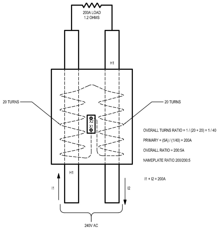
I have attached an image of what I believe to be the case for a 3-wire current transformer. My thought is these are wired such that there are two half coils internally wound in series as shown, is this accurate? If they were full coils then the measured current would be double of what it actually is since the current flows in and out of the current transformer and polarity is in series.

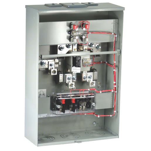
I also pictured an actual 3-wire current transformer for reference and its use in a form 3s meter.

Let me know if this is how it works.
3-WIRE_CT_hlmihf.jpg

3s_meter_h5cifr.jpg

Thanks,
 
Replies continue below

Recommended for you

In series you will get higher voltage at the same current.
The CT secondaries should be in parallel.

--------------------
Ohm's law
Not just a good idea;
It's the LAW!
 
Oh ok I think I see what you are saying so its really (2) parallel CT's each with the ratio of 80/1 internally. Since if you parallel (2) 80/1 CT's you will get a ratio of 40/1 which amounts to the 200:5A.
 
Actually I think I figured it out, the turns ratio is the same so it is still a single winding not (2) parallel. Thing is with the same conductor passing through twice even though the current is the same in both conductors (its seeing the 200A twice) now you have added a second turn to the primary side which will half the multiplier. So its still wound say 40:1 overall but now you have 2 conductors each carrying 200A running through the centerline of the CT so you now have two primary turns. So after that the ratio looks like 40/2. So if you passed 200A through in this arrangement instead of getting 5A out you would get 10A out. So naturally if the CT was wound such that it had a ratio of 80/1 the actual CT ratio with 200A expected to be going through the CT you would have 5A on the output. Since you doubled the primary turns you have to double the secondary turns to get the same ratio.

Basically I think the transformer has twice the number of secondary turns internally so that the ratio stays the same knowing that you created two primary turns in this arrangement.
 
I don't want to look for my metering handbook but as I recall, the KWHr meter has two current elements and each is fed by a 200/5 CT.
And for what it is worth, virtually all 120/240 revenue metering in North America is one element short of a Blondel solution.

--------------------
Ohm's law
Not just a good idea;
It's the LAW!
 
3S

A single window style CT is generally used, wired so it has two primaries of opposing polarity. One could use two CTs, but it would be more costly.
 
A single window style CT is generally used, wired so it has two primaries of opposing polarity.
That is, L1 and L2 pass through the CT window in opposite directions.
You may need a little more space in some cases.

--------------------
Ohm's law
Not just a good idea;
It's the LAW!
 
Status
Not open for further replies.
Back
Top