Mr. Che said:
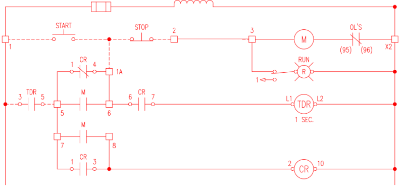
c) In both circuit 1 and 2, the O/L N.C. contact placed between M coil terminal b and the grounded line is a violation of NEC/CSA. Reason: In case the M coil terminal b is grounded, the system remains running until the motor is burned out; even the O/L N.C. opens.
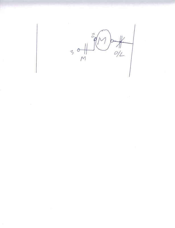
Shown here is typical factory pre-wiring of a typical magnetic motor starter in North America.
This is an approved assembly, and the NEC rules for field wiring do not apply.
Regarding your concern;
"Reason: In case the M coil terminal b is grounded, the system remains running until the motor is burned out; even the O/L N.C. opens."
The wire connecting the M coil to the O/L N.C. is a short jumper between the coil and the overload relay, both of which are mounted on the same base plate.
There are exceptions, but they are special orders for very rare special applications.
[Anecdote Alert] Yes, I have encountered special applications where the factory wiring of the O/L circuit was altered.
I specially remember it as the alterations included mistakes in the circuit that required the field rewiring of over 20 MCC buckets in the field.
The unintended consequence of the change was the self destruction of contactors under unanticipated operating conditions.[/AA]
I repeat, that the wiring of the overload relay is part of an approved assembly and therefore is not an NEC violation.
Well over 99.99% of magnetic motor starters supplied and installed in North America are pre-wired this way.
TYPICAL STANDARD WIRING OF A MAGNETIC MOTOR STARTER
Automatic Restarting:> This is application specific;
Canadian Electrical Code said:
(a) when automatic restarting is liable to create a hazard, the motor control device shall provide low-voltage
protection; or
(b) when it is necessary or desirable that a motor stop on failure or reduction of voltage and automatically
restart on return of voltage, the motor control device shall provide low-voltage release.
Low Voltage Protection: No Automatic Restart.
Low Voltage release: Automatic Restart.
--------------------
Ohm's law
Not just a good idea;
It's the LAW!