Navigation
Install the app
How to install the app on iOS
Follow along with the video below to see how to install our site as a web app on your home screen.
Note: This feature may not be available in some browsers.
More options
Style variation
-
Congratulations JStephen on being selected by the Eng-Tips community for having the most helpful posts in the forums last week. Way to Go!
You are using an out of date browser. It may not display this or other websites correctly.
You should upgrade or use an alternative browser.
You should upgrade or use an alternative browser.
3 wire motor control with delay 3
- Thread starter EricElec
- Start date
- Status
- Not open for further replies.
@ Mr Heaviside1925
"...IF providing a more robust and reliable control circuit is not feasible, I would consider the safest option would be the use of a small UPS in each bucket for the control power..."
1. Please clarify "use of a small UPS in each bucket" Some plants may have say 30-40 buckets, the proposal would not be cost effective. Usually the bucket are rather small in size and the UPS would take up the limited room available. How you seem it been done ?
2. I can understand if ONE rather small UPS for the whole control supply. Not for maintaining the power to the motors.
Che Kuan Yau (Singapore)
davidbeach
Electrical
If standard, unadulterated, 3 wire AC motor control doesn't get it for you, for any of a variety of perfectly valid reasons, you need to move to DC control from a battery backed source, stations batteries preferably, but some sort of "UPS" often substitutes. Now with a control source that isn't subject to momentary dropouts, provide the necessary protection and control to determine what can and can't be ridden through.
But dropping a motor for some transmission fault and then picking it up again a few cycles later can do nasty things. If you're going to ride out system transients, stay connected throughout the entire transient. If you're not going to stay connected, and you don't have any reconnection supervision, let the motor stop and then do a normal restart, provided, of course, that it doesn't need cool down time ahead of the next start.
When one this sentence into the German to translate wanted, would one the fact exploit, that the word order and the punctuation already with the German conventions agree.
-- Douglas Hofstadter, Jan 1982
- Moderator
- #23
I was faced with an automatic start compressor that was limited to three starts per hour.
In addition to cycling off the compressor was fitted with an unloader.
I arranged a timer so that the motor could not be started until the twenty minute time had expired.
Then, the motor was always ready for an immediate start if the pressure control demanded a start.
Has the EricElec made it clear whether he wants a ride through or wants a delayed stop?
I may have missed that.
For a momentary ride-through of a few cycles, it won't take much battery capacity to put the entire MCC on a UPS.
--------------------
Ohm's law
Not just a good idea;
It's the LAW!
@ Mr EricElec
and Hi to others
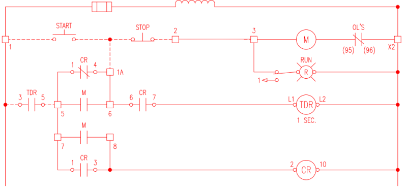
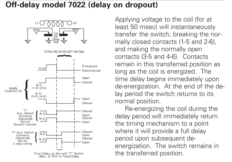
1. There are numerous learned advice on the circuitry, some misinterpretation and without knowing the intention. This is caused by the WRONG symbol been used on the TDR N.O. (3) (5) contact and without reading the development diagram.
" it is a N.O. contact which closes instantly when energized, but delay open (after 1s as shown on the dwg), when de-energized"
2. There are other flaws/short comings as pointed out by learned readers.
a) e.g. To Stop the motor, the Stop N.C. pb MUST be pressed open for > 1s. Propose addition of (latching-in) e-stop etc..
b) The OL's N.C. contact (95) (96) shown between coil M and line X2 is Wrong. This is switching on the grounded Neutral line, a violation of IEC/IEEE/NEC/CSA document. It shall be wired ahead of coil M.
c) Line Terminal 1 is shown Fused but Line X2 shall be grounded (not shown on the dwg).
Che Kuan Yau (Singapore)
- Moderator
- #25
Despite your excellent technical knowledge, it is obvious that you have no actual North American field experience.Mr Che said:b) The OL's N.C. contact (95) (96) shown between coil M and line X2 is Wrong. This is switching on the grounded Neutral line, a violation of IEC/IEEE/NEC/CSA document. It shall be wired ahead of coil M.
You are also misinterpreting North American Codes and Standards.
Are you seriously suggesting that every magnetic motor starter in North America for over eighty years is wrong as it comes from the factory?
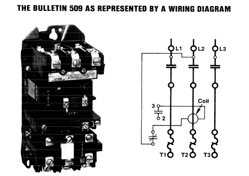
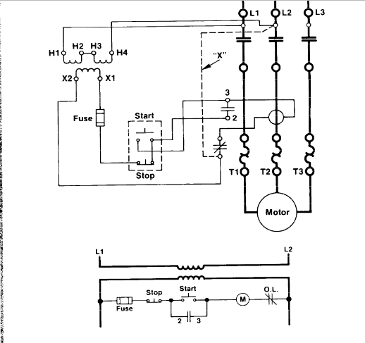
The Allen-Bradley brand as well as all other manufactures in North America publish standard wiring diagrams.Waross said:Shown here is typical factory pre-wiring of a typical magnetic motor starter in North America.
This is an approved assembly, and the NEC rules for field wiring do not apply.
This is a sample.
All brands publish and pre-wire to identical diagrams.
Across the line control:

Transformer Control:

--------------------
Ohm's law
Not just a good idea;
It's the LAW!
LionelHutz
Electrical
Well, I see some of the responses here are about as messed-up as that circuit is.
With a simple timer like that, you need a way to separate the timer action from a power loss or stop button press, which means CR is required.
With a simple timer like that, you need a way to separate the timer action from a power loss or stop button press, which means CR is required.
@ Mr waross
1. I stand by on my words, that switching placed on the grounded neutral is technically WRONG.
2. No matter what has been the practice in the US for the past 50+ years. This mistake also appeared in the NEC 1999 Handbook page 485 Fig 430.17 .
A mistake is a mistake, no matter how long the mistake has been in practice.
3. A similar case, the use of two heater overload for three phase motor had been the practice for the past 60+ years ! It is only recently that the mistake been corrected that three heaters shall be used on the three ungrounded conductors.
Che Kuan Yau (Singapore)
Heaviside1925
Mechanical
che12345
There are small din rail mounted UPSs, that could be used for one bucket. I am not advocating for this method to be applied universally across the site, which as why I added "on an as needed basis". I also included a qualifier, "If upgrading the control power is not feasible". I would assume that the power is not this unreliable across the entire site or else I would assume that there are more expensive issues. I would advocate that unless the site determines, it is cost effective to provide a more reliable source of control power, the only option would be more localized, i.e. per plant, per MCC room, per MCC section, per bucket. I would consider any of these options depending on the pervasiveness of the power problem and the budget the facility or the OP has to work with.
Other than providing reliable control power, the NEMA example that waross provided, I would think to be most appropriate with the addition/retention of a CR if DCS or other control, monitoring interface is typical throughout the site. I would not advocate for the TDR in this usage. For motor protection and reliability, I would advocate for the addition of a suitable power monitor interlocked with the stop circuit, with the parameters set for use specific application.
- Moderator
- #29
Recently in Canada was about 50 years ago.Mr. Che said:3. A similar case, the use of two heater overload for three phase motor had been the practice for the past 60+ years ! It is only recently that the mistake been corrected that three heaters shall be used on the three ungrounded conductors.
Your insistence that millions of starters and millions of electricians and engineers are wrong, in several countries, does much to detract from your credibility when your suggestions are correct.
The wire that you are concerned with runs from the starter coil to the attached overload relay.
It is often only a few inches long.
The wire of interest is typically not long enough for any part of the wire to reach any grounded surface.
--------------------
Ohm's law
Not just a good idea;
It's the LAW!
Agreed; che12345, I have often found value in your posts. Please don't "shoot yourself in the foot" by inflating theory over practicality to such an extent; if you persist in this, you only do yourself a major disservice.
CR
"As iron sharpens iron, so one person sharpens another." [Proverbs 27:17, NIV]
CR
"As iron sharpens iron, so one person sharpens another." [Proverbs 27:17, NIV]
- Status
- Not open for further replies.
Similar threads
- Question
- Replies
- 10
- Views
- 8K
- Question
- Replies
- 3
- Views
- 6K
- Question
- Replies
- 2
- Views
- 6K
- Locked
- Question
- Replies
- 12
- Views
- 6K
- Locked
- Question
- Replies
- 10
- Views
- 4K


