Continue to Site

Eng-Tips is the largest engineering community on the Internet

Intelligent Work Forums for Engineering Professionals

  • Congratulations waross on being selected by the Eng-Tips community for having the most helpful posts in the forums last week. Way to Go!

300 Series Flange 2

Status
Not open for further replies.

Wayne Falco

Military
Dec 3, 2018
10
Greetings,

I have been assigned to change our 150 psi for 1-1/4" pipe to 300 psi. I have near zero knowledge of piping.

I am attaching what I am now using for 300 psi flanges. My real question currently is what the dimension currently at .298 should be? How much compression? I can't seem to locate that detail. Currently I show line to line nominal.

Thanks,

Wayne
 
 https://files.engineering.com/getfile.aspx?folder=4407ba25-2e90-4a41-9deb-da1e7ac0726e&file=300_flange_layout.pdf
Replies continue below

Recommended for you

You're going to cut out all the 150# flanges and install 300# flanges?
 
Well the flange mentioned does not look to me like an ASME B 16.5 class 300 flange, but seems to be some sort of special flange limited to 300 psi.

It's this one
Anyway the gap you mentions is composed in part of a raised face (0.06") on each flange and gasket of 0.175" thickness.

The gasket will compress a little but I wouldn't have given it much more than 15-20% compression. So if you 0.298 goes to say 0.275" you won't be far away IMHO.

Quite why you want to change flanges is unclear and a little strange, you need t be sure nothing is getting over stressed, but I guess you're only interested in the piping layout?

I don't think you've drawn it right though. There is an upstand and a socket for the pipe in the flange. The PCD for the bolt looks wrong. And I've no idea how you're going to build it??


Remember - More details = better answers
Also: If you get a response it's polite to respond to it.
 
RVA... & Little...,

The tapered pipe is ours.

"does not look to me like an ASME B 16.5 class 300 flange" - are you saying 6806k289 is not a 300 psi flange? The tapered tube is not ASME. As far as calcs go. I will leave that to the egg heads running analysis.

Great - you answered the main question about compression. What I was looking to do was use that to determine the bolt height. The hardware for bolt and cotter pin has been updated. I think this all works?

"why you want to change flanges is unclear and a little strange" - I believe the pressure requirement is now max 300 psi.

"I don't think you've drawn it right though. There is an upstand and a socket for the pipe in the flange. The PCD for the bolt looks wrong. And I've no idea how you're going to build it??" - See new pdf. I have updated hardware. "There is an upstand and a socket for the pipe in the flange" - ???

I am getting more than I asked for....and I am grateful! Thanks! [bigcheeks]

Wayne
 
 https://files.engineering.com/getfile.aspx?folder=1fb373a0-cec8-497e-8eaf-233285d22a4f&file=300_flange_layout.pdf
In piping terminology, there is a flange standard called ASME B 16.5. It has various pressure ratings of flanges termed Class 150, 300, 600, 900, 1500 and 2500.

Unfortunately these numbers now mean very little in terms of actual pressure ratings which vary by material and temperature. Despite sometime erroneously referred to as 150 lb flange, this is NOT a pressure rating. If however you call your flange a 300 series flange there is an understandable thinking that you mean these flanges.

Your particular flange is apparently to ASME B 16.5, but somehow they have limited it to 300 psi at 300F. It's all a bit strange and doesn't match what anyone else would think of as class 300 flange which should be good to at least 600 psi at 300F.

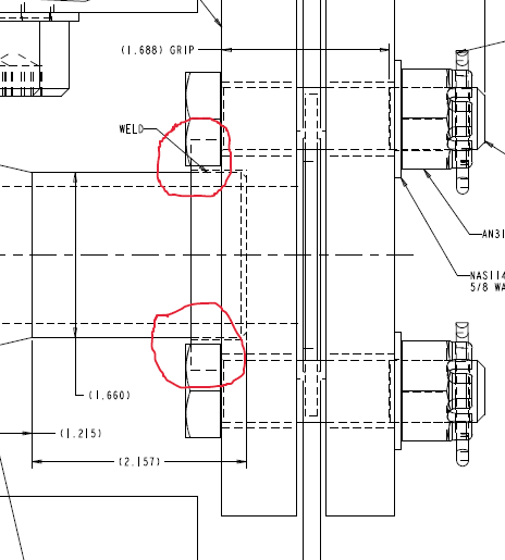
See below for what I mean about the upstand . It looks to me like you haven't allowed for the socket weld upstand and your bolt head is clashing with it (circled in red). Please check your bolt PCD.

also how are you going to get a spanner or socket onto the head of the bolt? It looks like it's sunk into a pocket inside the machine?

scan_ld6db2.png


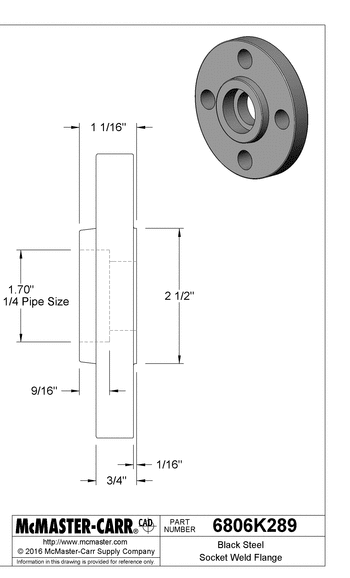
This diagram shows the upstand

flange_dtm4oa.png


Remember - More details = better answers
Also: If you get a response it's polite to respond to it.
 
To get one thing out of the way. I do have clearance for the bolt heads. A socket or wrench would work. See attached.

As far as the 300 series vs 300 psi. Well. This is where I fall short of knowledge. May need to speak with someone here. I recall being asked to change out what we currently have from 150 series to 300 series. Keep in mind, this is water running thru this. The temperature...I am not sure.

What I can do is whip up a layout of the 150 version of this. Maybe you can help me get what I am looking for or confirm what I have is ok?

Much appreciated! I will send a follow up of the original 150. Basically what I did was step it up from 150 to 300 on mmc. Perhaps erroneously like you say?

I am basically on loan to a project that is in trouble and needs support. Ergo, this really is not my expertise.

Thanks,

Wayne
 
 https://files.engineering.com/getfile.aspx?folder=5552c3eb-b0ed-4458-90b0-a4e02e76bfe6&file=25.PNG
OK, but your 3D model doesn't match the section view you posted - The bit I highlighted isn't 0.25" off the hub point. However in reality your flange as supplied will be as per your 3D model.

what I meant was that it looks like you couldn't actually access the boltheads with a spanner or a socket due to the surrounding casting

Anyway you have to fit what was being asked - my point was simply for information that the flange you're putting on looks like a "special" to me.


Remember - More details = better answers
Also: If you get a response it's polite to respond to it.
 
BTW....That view is misleading, as the bolts are turned 45 degrees. The 3d shows the actual.
 
I finally got the section view. It isn't what I normally see on a flange section and confused me.

Remember - More details = better answers
Also: If you get a response it's polite to respond to it.
 
Yes, but not quite sure what the question was. The attachment to the post at 1443 looks to be the same as the 300 series drawing? Did you mean to send the old 150 series one?

Remember - More details = better answers
Also: If you get a response it's polite to respond to it.
 

This pdf shows the 150 to 300 part number change, just showing the rational I used in picking the 300 ones. They say they are 300 series and rated for 300 psi as the 150 also stated.

I remember you saying something about misunderstanding the series vs. the rating.
 
What I meant was that the 300 series flange you're using is rated for 300 psi up to 300F.

In many piping systems a "Class 300" flange to ASME B 16.5 would be capable of much more pressure at that temperature.

your flange is a vendor special (I think) and its rating is lower than you would normally assume so it just needs noting on the drawing that the design pressure of your "series 300" flange is 300 psig @ 300F. Otherwise if someone else thinks this is a "class 300 flange to ASME B 16.5" then they could overpressure the system.


Remember - More details = better answers
Also: If you get a response it's polite to respond to it.
 
Are you saying the what I have is NOT ASME B 16.5?

I'm missing something.

One thing to keep in mind, that you would not know because I can't share too much of the design...is that this is part of a system that the pressures should be known and not exceeded. I am not sure what the max pressure rating is currently established at. I guess, I need answers from my guys. It's been tough though getting feedback.

Are you saying I can get a 300 series with greater than 300 psi?

Sorry, I'm really out of my expertise here.
 
It's a bit odd. The dimensions of the flange match that of a 1 1/4" class 300 flange to ASME B16.5 including bolt sizes and everything.

Whilst "black coated steel" is rather vague in terms of material, even the most basic Carbon steel in ASME B 16.5 would give you a pressure rating of 655 psi @ 300F. In fact their data sheet states a material at the bottom of A105 so this is all good. Why McMaster Carr then decide to de-rate this flange to 300 psi @ 300F is beyond me.

However if the pressures in your system are known and can't be exceeded you're going to be OK in terms of pressure rating.

hope that makes some sense to you.

Remember - More details = better answers
Also: If you get a response it's polite to respond to it.
 
Yeah - I think I know what your saying. Thank you so much for bearing with me on this. I will submit the drawing for review. Thanks!!!
Have a great holiday season!
[santa]
 
This is one of those cases where the McMaster catalog is wrong. They are just populating the max pressure with the pressure class for some reason. I purchased this blind flange recently and received a normal stamped B16.5 304/304L blind flange.
 
That's a good catch, jojoyohan.

The wonders of automation can also be frustrating and probably also dangerous in some rare cases.

I recently spent too much time trying to download the correct 3D CAD model for a ball valve c/w actuator. After assuming *I* was at fault for the first three wrong results (it is a multi-step, drop-down menu selection process to specify the file to be downloaded) it turned out that the same 3D valve model would be downloaded even if a different pipe size was chosen (verified by checking the "official" documentation for face-to-face dimensions).

Should I expend further time and energy convincing a giant company that they need to do some quality control on their digital catalog?


Status
Not open for further replies.

Part and Inventory Search

Sponsor