Eng-Tips is the largest engineering community on the Internet

Intelligent Work Forums for Engineering Professionals

32-pole motor winding with 96 slots 3

Status
Not open for further replies.

EngRepair

Electrical
Oct 13, 2012
49
0
0
HR
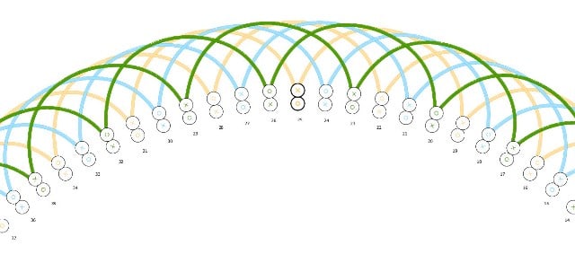
Does anyone else see something very strange in this unusual diagram?
It is a three-phase, double-layer 32-pole motor winding with 96 slots.
Is this connection correct?
If so, are there any benefits?

96_32a_a4_-_Copy_dpdmkt.jpg
 
Replies continue below

Recommended for you

4 circuits.
It should work but at first glance seems to me that half of the coils are wasted because of the extended pitch.
Pay attention to all the slots where the coils are marked with the same color. Current flows in opposite directions, and there is no torque contribution from these coils.
Am I right?
In addition, the winding factor of such a winding is probably very small. Incomparably smaller than the standard winding with pitch 1-4.
 
I'm not a winder.

96 slots, 32 poles...

If it was a standard winding there would be 32 groups per phase (with alternating polarity) and one coil per pole-phase-group. If it was full pitch, coil span would be 3 (1-4)

This has 16 groups per phase (with all same polarity), 2 coils per group, coils span 6 (1-7). So I agree with edison, this is a consequent pole connection which would have the same sync speed as a "standard" 32 pole motor (225rpm sync speed at 60hz or 187.5rpm at 50hz).

I agree with you Eng-Repair it looks like half the slots have the same phase with current flowing in opposite directions in top/bottom coil ... so it seems that half are effectively wasted. That is an expected consequence of the polarity requirements of consequent pole (all coils in a phase have the same polarity, so if top and bottom coils in a slot are same phase then the associated currents are in opposite directions in that slot).

I’d be interested in your opinions, what would be the downside of standard full pitch winding, one coil per group, coil span 3 (1-4) ? The connections might be messier but it seems like it would make much better use of the slot copper.
 
The pitch is 1-6.
(Btw, I came across this diagram looking for an option to redesign the motor (96 slots, 8 poles) to the highest possible number of poles.)
Apparently, it's consequent pole winding with extended pitch and I really don't know why pitch 1-6 was chosen.
As for the standard winding with pitch 1-4, it is certainly a better option because the winding factor is equal to 1, unlike the one shown which is supposed to be 0.433.
If I remember correctly, in some Easa publications I found that the full pitch should be avoided in case of double-layer winding, although I don't know why.
 
I guess the reason for avoiding full pitch must be related to spatial harmonics.

Full pitch means top and bottom coils in a slot will always be from the same phase. So in a winding of full pitch coils, when we transition from a belt of phase A to a belt of phase B', we have an instant 60 degree phase difference between adjacent slots (A A current in one slot, B' B' current in the next). But with less than full pitch coils there would be at least one slot in between which had both A and B', so the phase of that slot is halfway between... which means that the 60 degree jump gets broken into two jumps of 30 degrees between adjacent slots (A A on one slot, A B' in the next slot, and B'B' in the slot after that). Smoother change, less harmonics.

What is the practical consequence of this particular variety of harmonics? I have no idea.
 
Dear All,

This one should be a small motor so harmonics can be handled. It is possible to redesign to lap winding but with two different coils per slot you will need to add a separator and maybe there is not enough room in the slot for it.

Even though the preferred pitch should be 1-4 the designer chose the 1-6 pitch for ventilation matters. With 32 poles the RPM will be very low thus the 1-6 pitch is a wider pitch(wider coils) and the winding will be ventilated better than using a 1-4 pitch.

EngRepair, if you were looking for an option for redesigning this motor to 8 poles, unless the rotor is skewed, you should verify the slot stator vs rotor bars combination because someone can produce noise, Cusp, or Cogging.

Regards

Petronila
 
It looks like the diagram comes from some kind of book or internet, which means nothing.
Many books, publications, etc. can be found online that are worthless, accidentally or intentionally.
As for the given diagram, if it is a motor with one winding, it is a completely failed design. This is a winding with a very low winding factor and a very high content of harmful harmonics (almost five times higher diff. leakage coeff. then the standard one with span 1-4).
At first glance, the only reason for using such a winding could be if the motor contains one or two more windings (common case at crane motors), to avoid the magnetic connection between energized and non-energized windings. Or its purpose is only for a few seconds at startup (something like a PWS). Maybe.
But this topic opens up another dilemma:
It is well known that a two-layer lap winding can be made with a shortened or extended span.
So far I couldn't find an answer anywhere to the question: to what extent, i.e. how much can the span be shortened or extended. Let's see what would happen if the mentioned winding was done with span 1-7 (see the figure below). It would no longer be a motor at all.
It is similar case with the shortened step. For example, whether a 48 slots, 2 pole motor be made with a span of 1-17 or 1-6 or 1-2, regardless the bad winding factor and harmonics? Theoretically, where is the limit?


acw-_jvlkjz.jpg
 
Status
Not open for further replies.
Back
Top