Eng-Tips is the largest engineering community on the Internet

Intelligent Work Forums for Engineering Professionals

3CW-FF Vs 3CW-BB

Status
Not open for further replies.

fsxn155

Mechanical
Jun 29, 2020
29
0
0
QA
Dear All
We are facing problem of repeated premature Mechanical Seal Failures on 03 Multi Stage Centrifugal Pumps in our Refinery. The Problem is since commissioning and Seal manufacturer has done some modifications but problem has not been resolved.
While comparing Seal Arrangement on all Pumps in this Refinery as well as another similar/twin Refinery, I have found that the 03 problematic Pumps have 3CW-FF Seal Arrangement. All other Pressurized Seals in both Refineries are 3 CW-FB or 3CW-BB.
Another observation in addition to the subject 03 Pumps, another Pump in same Refinery had 3CW-FF Seal which suffered repeated failures and was latter modified to 3CW-BB by Seal manufacturer
I have gone through API-682 and what I understand is that 3CW-FB is preferred arrangement for Pressurized Double Seals. I appreciate if someone can explain the positives and negatives of these arrangements
 
Replies continue below

Recommended for you

Many people on this site may not be familiar with these coded designations. For their sake, I will try to clarify. All of these seals are contacting wet (CW) seals of Category 3 (high temperature) set up as pressurized double seals. The last two letters designate if the configuration is Face to Face (FF), Face to Back (FB) or Back to Back (BB). Please correct me if I have misinterpreted this.

There are a few differences that come to mind to distinguish between these arrangements. Without a seal drawing, I will have to make some assumptions. Depending on the pressure balance of the seals, there can be a big difference in how they react if the pressure between the seals is lost. The face to back arrangement is what some of us old-timers would have called a tandem arrangement. This can be pressure balanced such that the seal continues to function as a double seal even on loss of barrier fluid pressure. Leakage would have to make it past both seals to leak to atmosphere. The face to face or back to back arrangements might function as a single seal on loss of barrier fluid pressure since one or the other seal could not function under reverse pressure. One set of seal faces would be forced open by the reverse pressure. This can have a large impact on safety depending on your service.

There is also a difference based on where the potentially dirty product contacts the inner seal and whether the seals are stationary flexible elements or rotating flexible elements. If the dirty product in on the inside diameter of a rotating seal, any solids present can be centrifuged outward plugging the seal up. For dirty service, it would usually be preferred to use a stationary flexible element or to have the dirty product on the outside of the seal.

Any sort of drawing of the face to face seals that have been failing would be helpful. A description of a typical service would also help.

Johnny Pellin
 
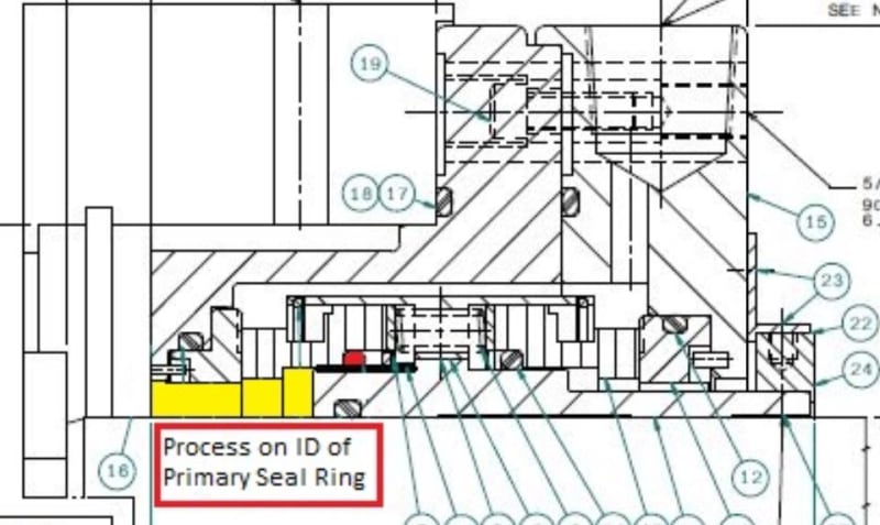
In a critical, unspared charge pump, we had a dry gas seal that was in this back-to-back arrangement:

Capture_b6dxzv.jpg


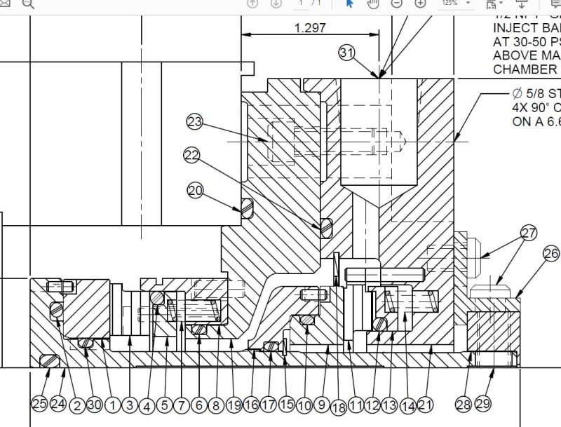
The seal was failing often from the inner seal getting packed up with solids from the dirty product. We converted to a face to back arrangement like this:

Capture2_wjr7nk.jpg


Our reliability has been much better since then.

Johnny Pellin
 
Dear Jhonny
Thanks for reply. Seal Cross Section is attached. Will u plz also help me understand how 3CW-BB & 3CW-FF compare. Our experience is that 3CW-BB are running acceptable whereas we are having problems mostly with 3CW-FF. In fact as I mentioned in one of Pumps Seal manufacturer has changed Seal Design from 3CW-FF to 3CW-BB
 
 https://files.engineering.com/getfile.aspx?folder=9d6a2031-60e2-4078-b059-a777f483b244&file=Untitled.jpg
The face to face drawing you provided has the pumped product on the inside diameter of the inner seal. Both seals are stationary bellows with normal outside diameter pressure. The fact that the mating ring on the inner seal is retained suggests that the inner seal is balanced for some amount of reverse pressure. The stationary bellows design is good from the standpoint of seal chamber face run-out. A stationary bellows will not have to flex with each shaft rotation and will be less likely to fatigue and crack at the bellows core.

But, even though the inner bellows is not rotating, it can still pack up with solids from the spinning shaft throwing them outward. The faces on that inner seal look like a very aggressive pressure balance in order to allow for loss of barrier fluid pressure without those inner seal faces blowing wide open. This balance probably creates some compromise in terms of face loading when the seal is running normally with full barrier fluid pressure.

If all they did was reverse the parts to make this a back-to-back design, then it would become a rotating bellows on both the inner and outer seal. This is bad for accommodating seal chamber face run-out. And, the likelihood of solids getting driven into the convolutions of the bellows by centrifugal force would be worse. If the seals are running better that way then the failures are probably not related to solids in the dirty process or bellows fatigue. That leads back to the face pressure balance. With the bellows stationary as in this face-to-face design the pressure rotation of the face will tend to drive toward OD high to make a divergent face gap. Temperature rotation of the face will ted to drive toward ID high and a converging face gap. Once you change to a rotating bellows, you add a third force related to the face gap. The spinning bellows will tend to drive toward an ID high condition and a converging gap. A diverging gap can be a problem in terms of maintaining a good fluid film and limiting face heat generation.

You should be able to examine a failed seal and see the evidence if I am right. The mating ring would have a hard wear track at the outside diameter of the primary ring indicating OD high and a diverging face gap. Of course all of this assumes that your leaks are primarily internal leaks with barrier fluid leaking inward through the inner seal into the process.

Johnny Pellin
 
Hi Johnny
Just to clarify I have not said they have modified this Seal to 3CW-BB. The Pump under discussion say "Pump A" has same 3CW-FF Seal as per Dwg I have provided.

It was on another pump (say Pump "B") where initially Seal was 3CW-FF Pusher Seal and latter they changed it to 3CW-BB Pusher Seal. The point I am trying to mention is that at our plant, we have most Dual Pressurized Seals in 3CW-BB arrangement which are working fine.

Very few Seals are in 3CW-FF arrangement and most of them have been problematic right from the beginning. In fact on one pump they changed 3CW-FF Pusher Seal to 3CW-BB Pusher Seal

I hope I am able to clarify.
 
I must not have been clear. I was speaking in the theoretical. I think the main difference that makes BB work better than FF is related to the pressure balance of the faces and the ability to maintain a uniform fluid film across the seal faces. This is true of a pusher seal or a bellow seal. Just substitute "fretting under the dynamic o-ring" in place of "bellows fatigue". It could also have to do with the location of the barrier fluid in and out connections relative to the seal faces. they might be getting better fluid circulation with the BB seal and have less heat build-up at the faces as a result. If that is the case, you should see signs of heat damage or flashing at the faces. In any case, you need to examine failed seals to see why they are failing and that will lead you back to the common cause.

Johnny Pellin
 
You never said what flush plan is used. Are these Plan 53a, 53b or 54? In any case, the seal in the report ran without barrier fluid pressure for quite a while. This would have resulted in failure whether BB, FF or FB. Perhaps FB might survive a little bit longer.

Johnny Pellin
 
Dear Johnny

Sorry for incomplete info. The Flushing Plan used is API 53B. The normal Seal Chamber Pressure is 3.5 barg and can go maximum up to 7.7 Barg. Mating Ring is Reaction Bonded Silicon Carbide & Primary Ring is Carbon. The product Temperature is 257[sup]0[/sup]Celsius. Normal operating Barrier Fluid Pressure is 9 barg to 9.5 barg against recommended Barrier Fluid Pressure of 11.7 barg. There is low pressure alarm at 8.7 brag for Seal Oil Pressure.
During recent Seal Leak event, the pump was normal on standby and when it was started, immediately there had been external leak reported from this Seal. Once the Leak Started, the Seal Oil Pressure dropped and there had been frequent refilling of Seal Oil System. Seal Oil Pressure dropped to minimum of around 4 barg during this event.
The available Seal Oil Pressure Trends indicate that once the Leak Started, Seal Oil Pressure was maintained at around 7.2 to 7.3 barg by continuous refilling for around 10 - 12 hrs and latter Pump was Stopped.
[highlight #FCE94F]I have attached 16 hrs Trend of Seal Oil Pressure along with Pump RPM.[/highlight]
Just for sake of my understanding, I believe you conclude Seal ran without Barrier Fluid Pressure based on Black Sludge/Coking which most probably seem to be coming from heavy Carbon Face Wear?
Unfortunately right now I am unable to extract Suction Pressure Trend to confirm if Seal Oil Pressure at any point in time dropped below Suction Pressure. However even if this has happened, it's a secondary phenomenon. To begin with Seal actually started leaking immediately When Pump was started ?
As I mentioned before this Pump has history of Seal Leak since commissioning (by end of 2016). Seal manufacturer has changed Seal Oil Pumps from originally supplied magnetic Coupling Pumps to mechanical Coupling Pumps and added Flowmeter in Seal Oil System to ensure Seal Oil Flow. However the problem is still persisting
 
 https://files.engineering.com/getfile.aspx?folder=871d696f-32e8-42db-bcbb-b6c6de797bd8&file=Trend.jpg
Yes. I have assumed that you are not deliberately using black sludge as a barrier fluid. So, the presence of a lot of black sludge inside the seal suggest you ran without proper barrier fluid pressure.

A Plan 53B system would not normally include seal oil pumps. So, I am not sure what this part of your post is referring to.

I am running out of patience for asking questions and guessing. So, I will end with a few generic comments on failure causes that might be applicable to your pump:

The seal chamber pressure may be higher than you think it is. We have seen set up balance lines or various pump malfunctions that can cause higher seal chamber pressure. Unless you directly measure the pressure in the seal chamber, you may not know what it really is. But, since you have not mentioned the pump configuration or the service, I cannot be sure.

Plan 53B is prone to pressure fluctuations based on ambient temperature and sun/shade. We have had to add insulation and sun shades to some of ours.

I assume freezing is not a concern for your systems, at least not this time of year. We have seen freeze up because of the way our Plan 53B are piped and how they are filled.

This service is hot enough to require a very good heat up procedure with appropriate piping so that the entire pump (top to bottom) is heated up to within 100 F of the product temperature before start-up.

I hope that some of this is helpful. Good luck.

Johnny Pellin
 
Hi Johnny
Just to clarify your concern regarding Seal Flush Plan, refer to the attached Snapshot of Seal Flush System P&I Diagram

Your comments are very useful as all your guess is correct. There is no direct measurement of Seal Chamber Pressure. On Suction side there is only Pressure Gage and on Discharge Side there is no measurement at all of Balance Line Pressure. Also Pump has long Balance Line that returns Balance Drum Leak to Suction Piping at quiet a long Distance from Pump Suction Flange.

I hope to find some clues form here on in.

Thanks a lot for your time
 
 https://files.engineering.com/getfile.aspx?folder=1d89a174-7c9d-4f29-b323-41038e027912&file=Seal_Flush_System.jpg
Status
Not open for further replies.
Back
Top