Eng-Tips is the largest engineering community on the Internet

Intelligent Work Forums for Engineering Professionals

3rd party plan review reentrant corners

Status
Not open for further replies.

GVCivilGuy

Civil/Environmental
Jun 4, 2007
17
0
0
US
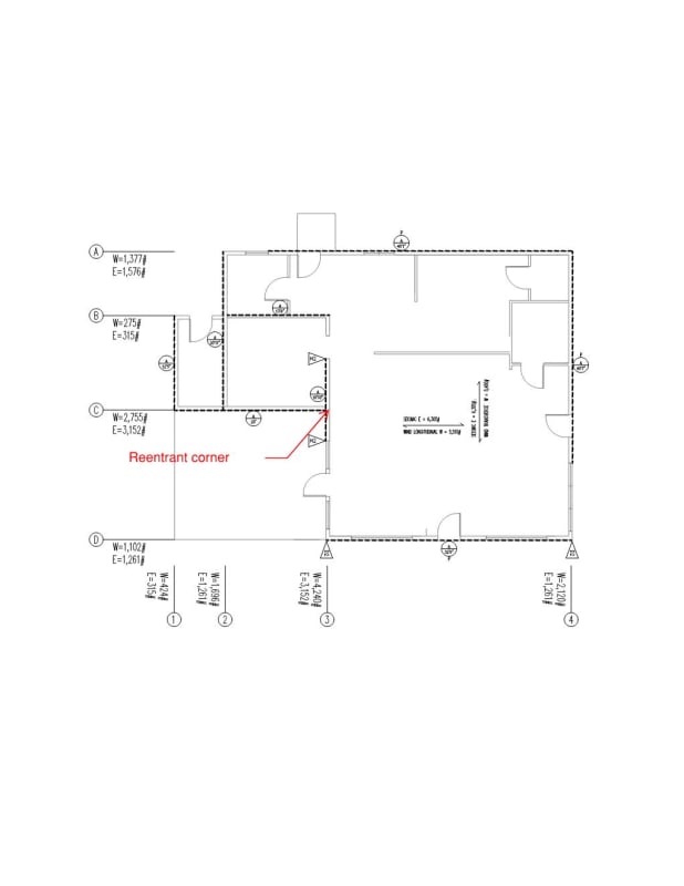
I have a single story residential project in CA, seismic design cat D. All of the municipalities have farmed out plan review to 3rd party agencies that throw the book at the plans during a review.
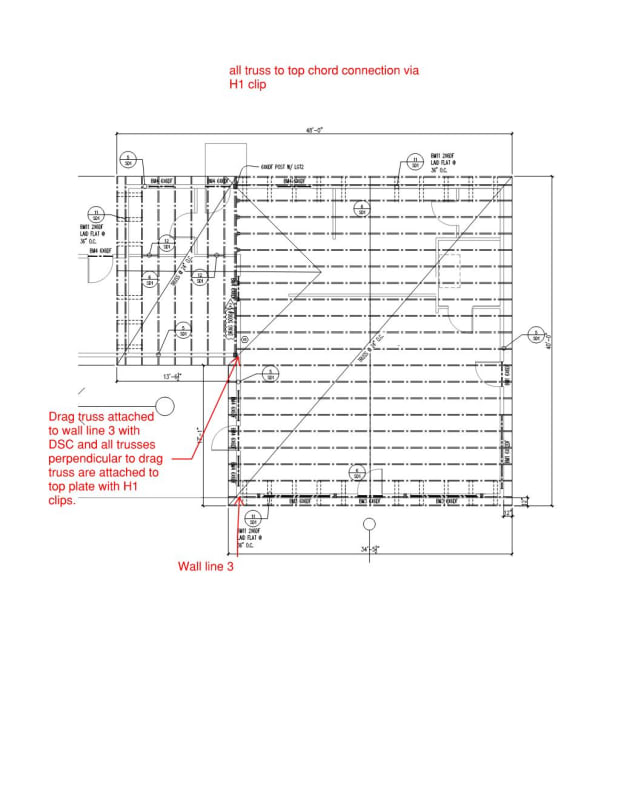
My current review is asking me to "At the horizontal diaphragm offset provide continuity ties in both orthogonal directions per ASCE 7-16 section 12.1.3 and 12.10.1." My response was Tributary roof areas adjacent to shear walls resist the horizontal diaphragm forces. There is no need for strapping as the roof sheeting provides continuity. Her response to me was: "PC2: Thank you for providing a response. However, continuity ties at the diaphragm’s reentrant corners with diaphragm straps are required. Please include per resubmittal." Technically per ASCE she is correct, but come on!
This is a light framed single story residence! I am not relying on transferring diaphragm forces from the main roof to the smaller gable because I have shear walls in all directions. I appreciate anyone's thoughts on how to deal with the situation or respond.
Here are the plans:
Document1_Page_001_xjdgap.jpg
Document1_Page_002_g0u1ao.jpg
 
Replies continue below

Recommended for you

Edit: I should completely change my first sentence to say, as drawn, I agree broadly with the reviewer, but that I think there is a better solution

I would argue the toss as I don't agree, assuming I've understood this correctly
Though noting that I work in residential design in New Zealand so "same same but different"

We have a clear distinction between a plain old "ceiling" and a "ceiling diaphragm"
A "ceiling" is good for up to 6m x 6m (~20' x 20') and doesn't need any real fancy trimming out etc, and we can use a specific "ceiling diaphragm" for up to 12m and 2:1 aspect ratio (12x6m)
We do not require diaphragm continuity throughout an entire house - only the area where it's relevant
So, in your case, I would expect that the 34'5" section would need a continuous diaphragm, which it has, and the other areas of the house area all less than 20' x 20' I think so just need a plain ol ceiling

I think that the wall between Grids B & C at the edge of the 34'5" room should be bracing to trim the diaphragm ceiling out in order to make this true
Otherwise your diaphragm relies on the Grid C bracing wall to tie it in - in this case you would need to specifically consider how your diaphragm performs as it isn't a proper four-sided box, it's more akin to a overhanging beam model as there is no support at the Grid B-C wall


I probably tend to agree with you, the diaphragm is actually 2 diaphragm regions each supported on both sides, each with continuous chords. However rather than try to fight the plan reviewer cant you just put a strap up there on top of blocking to the dbl top plate and make the reviewer happy?

The other approach would be to provide a FBD of the two regions separately and indicate that no load x-fer across the Grid Line 3 is needed to meet the requirements of Section 12.10. Demonstrating the load path is resolved without a T/C couple from the small diaphragm should also satisfy section 12.10.

Just put some straps up there, no good ever comes from arguing too much with the reviewer. That would be my best advice :D Unlikey they are going to back off now, they already doubled down.
 
@Greenalleycat Since this is a gable roof, I don't think the ceiling diaphragm enters the equation. I also don't think it's an overhanging beam model because the diaphragm is fully connected (just missing connectors).

I'm not sure that the FBD will pan out the way you want because the diaphragm is connected and you can't treat it as two separate entities without an expansion joint. That's almost like analyzing a building with a tiny 4m X 4m bump as two separate buildings. While I agree with you that strapping isn't needed (nobody does it and roofs are still standing), I'm not sure how you can fight it with logic and forces. Maybe you could treat part of the diaphragm as a chord, but that's not supported by any book that I know. I agree with driftLimiter that it's just better to cave in.
 
Maybe I haven't understood the geometry properly, but what does it matter that it's a gable roof..?

Code here requires diagonal strapping in the roof plane, which is kinda a boxticking exercise as the roof sheathing will be way stiffer under lateral load, but I suppose at least stops the roof deforming until the sheets go on
Unless you're specifically doing a roof-plane diaphragm though then this has little influence on lateral load distribution as it's only taking care of the (small) roof-level weights (tops of trusses and roof cladding)

The clause in the OP references a horizontal diaphragm, which to me means a ceiling diaphragm, so I interpreted this as being about the distribution of loads at ceiling level
Under our code, if you want to use an intermediary wall (say the Grid C wall) as a bracing line, it needs to be connected across to the opposite exterior wall - this is basically what his drag truss with H1 connectors do
Think about the load path here though - ceiling collects loads into trusses, delivers into top plate via H1 connector, then how does the top plate deliver loads to the return wall? Perhaps there's a nail plate connector between perpendicular plates, but does that have sufficient capacity for the load?

I think the overhanging beam model is 'theoretically' correct because the non-bracing wall at one end has not been designed to support that edge of the diaphragm - so how is it not a cantilever?
I would just brace the Grid B-C wall and then the diaphragm gets nicely trimmed out on all sides by bracing walls and the ceiling can tie in really nicely
Now the diaphragm area is just a rectangle that has no requirements for support from elsewhere in the building

Now, regardless of theory, undoubtedly the building will perform how it wants to and damage could occur
Certainly that was a lesson from the EQs here - just connect stuff together and it performs well, don't connect it and it performs poorly
To me, that's what the H1 connectors and the nail plate at the top plate junction does - it ties things together

 
@Greenalleycat I think we're going to disagree about the overhanging beam thing, so I'll leave it at that. Anyway, I'm confused by the terminology because I've never heard of a ceiling diaphragm. Maybe the code is much different here in USA. We have roof diaphragms. The ceiling will never be sheathed in something like structural plywood or OSB; it'll always be gypsum board or a drop ceiling, which offers incidental lateral stiffness at best. So the roof is actually the horizontal diaphragm, even if it's not flat. I agree about the connectors; I also think if there's solid blocking between the trusses, that's a good way to connect directly from the diaphragm to the double top plate.
 
How do the straps actually work in a situation like this? Seems like you'd have a nasty, crossing hardware situation right at the corner with the drag truss running the other way.
 
If you can switch out the DSC for another strap that might be easier at the corner. Straps can sit atop the dbl plate and anchor to bottom chord of drag truss. Small clear distance on the strap in one of the directions to clear the other strap. Would need to figure a decent compression load transfer solution but this is usually not too hard usually.
 
@milkshakelake seems like there's a big regional difference in approaches here so I'll bow out as not the best person to comment

Dare I say, 99% of our diaphragms are ceiling level, and of those 99% are done with plasterboard
It's a rubbish product but we have a small market with some very entrenched interests who have sold the country on double-using plasterboard as both bracing and an aesthetic finish to save money on requiring ply....


kootK,
I agree with you, straps only work in tension. In addition I'm not dragging any load from that diaphragm beyond into wall line C. The ridge lines are perpendicular to each other. I was treating them as "separate" areas. Is my logic correct?
 
We typically put in straps in this situation. If you don't, I think one could argue you should put in a seismic joint per ASCE 7-16 12.1.3 which would be unusual in a residential structure. Redundancy in the system is good in seismic design. If the two pieces are completely independent of each other, there is potential for their frequencies to be different during an earthquake and for the two sides to pound against each other. Maybe in residential structures one could hand wave this away, and this structure doesn't seem very large so the concerns could be lesser, but we'd typically overdesign the shearwalls to account for different load paths and strap the two sides together at the reentrant corner.

Using a coil strap pre-nailed to the top plates than is then nailed to the underside of the truss could be easier to detail with than the DTC.
 
Does GV stand for Grass Valley? It's where I live in California and the 3rd party plan check comments look like this company that does our counties plan checks, lol. As far as your question...I don't have any real advice. Just wanted to say hey.
 
Status
Not open for further replies.
Back
Top