LQQD
Structural
- Apr 14, 2012
- 38
Hi everyone,
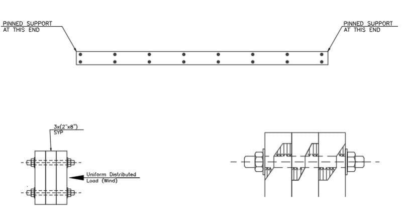
I am working on a timber structure, first time dealing with timber. All my design are based on AWC-NDS 2018. I am dealing with a 3 ply 2"x8" SYP single span pinned beam. Total beam length is 12ft subject to 60 plf wind load. In order to control deflection and strength I need the beam to work as a solid beam i.e. composite action.
Firstly I would appreciate if anyone has any suggestion on how to deal with this situation. Have anyone done this before? What do think about it? Do you have any reference?
I couldn't find any guidance in the specification or how to check this connection so I'm improvsing al little bit.
I was thinking on using bolts to transfer the required shear. Please find attached some drawings. On the bottom right I draw how I am thinking bearing stresses will be between wood and bolts. I am assuming the same stress pattern around each bolt.

It's an analogy to how stresses develop around a pile subject to horizontal load, assuming some plastification of the soil near the top. I took reference from some old graduate school notes.
Do you think this may be a valid stress diagram? do you know something more accurate? How about bolt spacing, any recommendation?
Suggestions welcomed!!!
Thanks!
I am working on a timber structure, first time dealing with timber. All my design are based on AWC-NDS 2018. I am dealing with a 3 ply 2"x8" SYP single span pinned beam. Total beam length is 12ft subject to 60 plf wind load. In order to control deflection and strength I need the beam to work as a solid beam i.e. composite action.
Firstly I would appreciate if anyone has any suggestion on how to deal with this situation. Have anyone done this before? What do think about it? Do you have any reference?
I couldn't find any guidance in the specification or how to check this connection so I'm improvsing al little bit.
I was thinking on using bolts to transfer the required shear. Please find attached some drawings. On the bottom right I draw how I am thinking bearing stresses will be between wood and bolts. I am assuming the same stress pattern around each bolt.

It's an analogy to how stresses develop around a pile subject to horizontal load, assuming some plastification of the soil near the top. I took reference from some old graduate school notes.
Do you think this may be a valid stress diagram? do you know something more accurate? How about bolt spacing, any recommendation?
Suggestions welcomed!!!
Thanks!
