Eng-Tips is the largest engineering community on the Internet

Intelligent Work Forums for Engineering Professionals

  • Congratulations waross on being selected by the Tek-Tips community for having the most helpful posts in the forums last week. Way to Go!

4-20mA Pressure sensor is noisy when the VSD is running or not.

Status
Not open for further replies.

davemcl

Electrical
Jul 19, 2020
9
0
0
ID
We have a custom built data logger with 4-20mA inputs that when tested with a current loop calibrator, the input is stable to 2 decimal places with the 3rd decimal fluctuating around +-0.003mA. The input has a 100 ohm resistor from the ADC input to ground. The ADC is a very stable 16 bit with the above readings.

The VSD is a 75KW Altivar model.

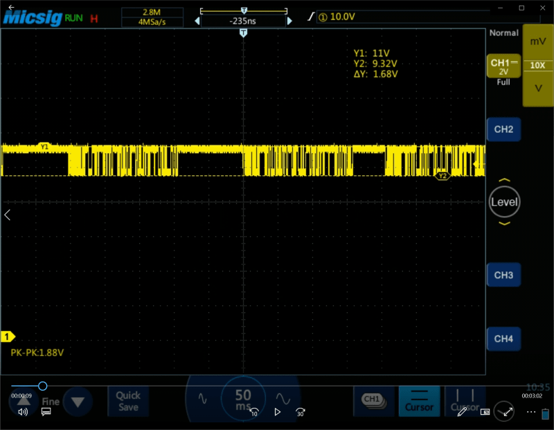
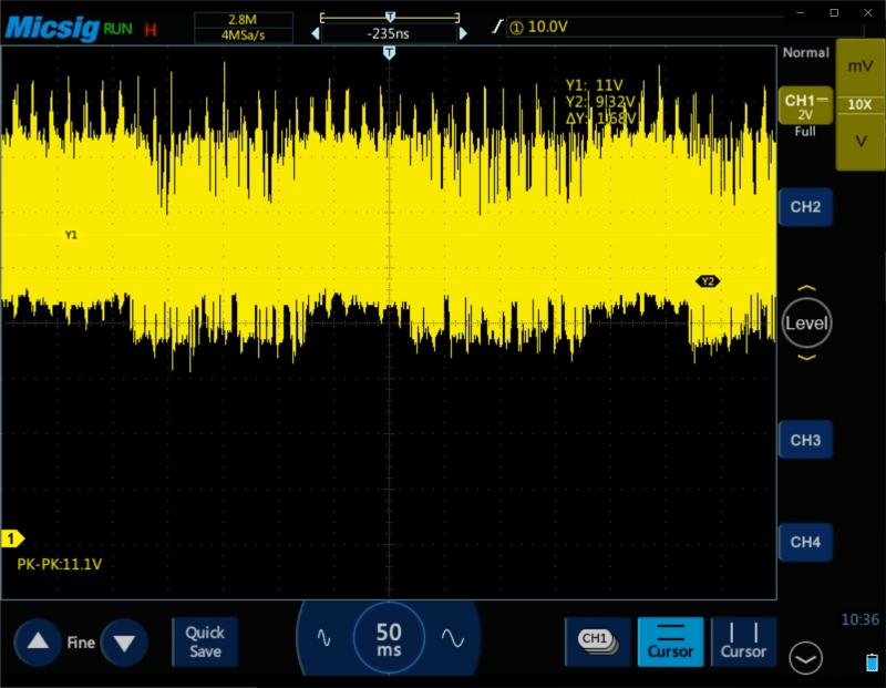
We have a client supplied sensor connected, Wisner WPT-80G-A7N2, 40 bar gauge, stated accuracy 0.5%, and with atmospheric pressure applied, fluctuates around -2 to 3 PSI with the VSD not running. The attached image shows the VSD stopped and then started and the increase on the sensor noise. I am waiting for a sensor to arrived to do some testing here in our workshop.

The client has connected the EARTH pin on the sensor to the VSD ground in the cabinet. Without this ground connection, the 4-20mA signal is sitting around 1.6mA ??? With it connected, the signal fluctuates around the 4mA point.

Sadly they have used 3 core flexible rubber cable of some 150 meters long and I suspect this has a lot to do with the issue.

We saw this issue of noise from the VSD in early testing at the clients workshop with our downhole gauge but we were able to fix this by connecting the gauge ground point directly to the VSD ground in the cabinet. There was a large ground loop between the VSD motor earthing and the gauge ground. As the 4-20mA sensor is isolated we cannot connect this to ground in the same manner.

The DC supply for the data logger has no internal connection from the OV output and the EARTH pin so the DC 0V for the logger is isolated from the VSD ground. We have a connection from this 0V to he VSD ground. Would isolating this be worth testing?


 https://files.engineering.com/getfile.aspx?folder=aa49b20e-f118-4ab7-9f63-01f8c537160a&file=vsd-noise.png
Replies continue below

Recommended for you

As a follow-up, I received a test sensor of the exact same model and it is stable when connected to our data logger in the workshop. No change in the out when the test VSD is running but mind you, that is only a 2KW version for workshop testing.

The client is now sourcing some screened twisted pair cable to test with tomorrow. We know this worked before on other wells so the fault has to be grounding.
 
Flexible cord. Ugh!

If this thing has nothing to do with the VSD I'd keep its ground as far as possible away from the VSD grounding. There is a large amount of high frequency current returning to the VSD directly from the motor's case. Some of it down the ground wire but a lot of it down any and all contiguous metal. Anything electrically connected to that same path will pick up some of that current/noise.

The sensor cable should definitely be shielded twisted pair and not rubber cordage which lacks reasonable twisting. Be prepared to connect the shielding only on one end and try each end to see which does the best job.


BTW: The motor ground should go directly to the VSD grounding point, then the other VSD grounding point should go to the system ground. Do not connect the motor ground to the system ground directly or the high frequency current returning from the motor will head out all the other grounds while trying to find its way back to the VSD.

Keith Cress
kcress -
 
Thanks Keith,

The issue is that the complete wellhead is mechanically connected to the motor housing and so is electrically bonded to the rest of the metalwork. The sensor is plugged into this wellhead so the body of the sensor is connected to the VSD ground via the wellhead. The 2 wires of the sensor are isolated from the grounded body but we are somehow picking up noise and likely due to the wrong cable. We will know tomorrow when they replace the sensor cable with proper twisted pair cable.

This VSD grounding has been an issue for some time. We had a big issue with the comms from the gauge being wiped out went the VSD was running. The motors on this are running at about 25% of their capacity due to the low pumping speed required. The motor is running at 300 rpm at present. It seems to vary from well to well as previous installations were fine with stable sensors.
 
Keith is spot-on. Without proper grounding and shielding you shouldn't be surprised with a noisy analog signal, especially when connected to a larger drive. You're also going almost 500' so that just makes it worse.

Brad Waybright

It's all okay as long as it's okay.
 
>The DC supply for the data logger has no internal connection from the OV output and the EARTH pin so the DC 0V for the logger is isolated from the VSD ground. We have a connection from this 0V to he VSD ground. Would isolating this be worth testing?

Yes. Can you float the 0V output and check the results?
 
Just a quick update on this issue, which is still not resolved. They replaced the 150m of rubber cable with a proper screened twisted pair. With the shield grounded at the VSD and the sensor in air, the signal is +-0.1 psi change so this looks good from the point of the data logger is able to read the sensor for a clean signal. The shield is not connected to the sensor body.

If we install the sensor on the wellhead, the noise is +-10 psi so not working. We have tried the shield connected at either end. In fact, with the shield connected at the sensor body and the sensor in air, we get around +-4 psi of noise so the correct ground is at the VSD.

The ground at the VSD end is the same ground that the downhole gauge is connected to and it is working fine even though its cable is also grounded at the wellhead due to the pressure seal. If we remove the downhole gauge ground at the VSD the gauge stops working due to the VSD noise. With it connected, the gauge is fine.

We have 2 such installations with this issue. The previous installations using the same sensors and twisted-pair worked fine.
 
The previous installations using the same sensors and twisted-pair worked fine.

Okay, what's the fundamental difference between this one not-working well and the two working well systems?

I'm also a bit confused down hole/well head? Is this the same sensor just 'tried' in the two locations or are there 2 sensors?

Keith Cress
kcress -
 
I have always grounded the shield at the control panel (measuring device) end and have never had an unacceptable noise problem. However, I believe I have never tried to use analog communication to a device over anything near to 150 meters. I'm trying to grasp the correlation between the VFD and the pressure sensor. I normally do not use the earth pin on a transmitter, as the device is inherently grounded by connection to process piping. I envision that your cable shield would be grounded at the control panel/datalogger location, and not at the sensor. Is the transmitter a 2-wire configuration or is power supplied separately? I don't believe grounding the sensor separately should make a difference either way. Also, not sure if your 24VDC supply is referenced to ground, VFD chassis, or other.

Brad Waybright

It's all okay as long as it's okay.
 
Keith, this is a wellhead for an oil well and we have 2 sensors. One is located 900 meters underground in the well measuring the pressure of the oil above the pump. The other sensor is located at the surface measuring the annulus pressure in the well. We subtract the annulus pressure from the downhole pressure to get corrected fluid height.

There is already a moving average filter on the sensor but the noise is too great with a large change that it doesn't work too well but I will see about ordering that filter you linked to and give it a try out.

I think the issue with this over the previous wells is how they have arranged the grounding at the well site. Sadly I am not able to visit the site and do testing myself but we did do some testing at the factory test well and the noise from this VSD is very bad and careful grounding is needed.

Brad. The 24V power is supplied by a separate DC supply that powers the data logger. The OV on this is isolated from the VSD GROUND and I am reluctant to connect this together as a few years ago we did this and it fried the DC power supply when the VSD was switched to run.

I'll let you know how that hardware filter works once we get some to try out.
 
Just for reference of how bad the VSD noise is, the 2 images here show the digital transmission from the downhole sensor before and after the VSD is started. The isolated handheld scope was connected across the power and ground connection. We transmit data over power as the cable is only single core with the outer metal jacket as the return (this is connected to the wellhead metalwork and hence the same ground as the motor)

beforepumpstart-existingground_aymkw6.png


afterpumpstart-existingground_jj2iyk.png
 
I had a case where EMI was not affecting the the 4-20ma signal, but was causing the sensor itself to misbehave. This was a submersible pressure sensor produced by a major player in that field. Again normal reading when the VFD was off, however when the VFD started, the level jump by several feet. Checked grounding, connections etc. Ended up replacing the sensor and that cured the problem. After checking the bad sensor it appeared to have an internal short between the electronics and the sensor case. Might be a pain in the you know what, but try replacing the bad sensor with a known good one.
 
>The DC supply for the data logger has no internal connection from the OV output and the EARTH pin so the DC 0V for the logger is isolated from the VSD ground. We have a connection from this 0V to (t)he VSD ground. (post #1, 20 July)

>The OV on this is isolated from the VSD GROUND (24 July)

The two statements make it unclear to me. Is the 24Vdc power for the signal connected to the VSD ground or not?
 
> The two statements make it unclear to me. Is the 24Vdc power for the signal connected to the VSD ground or not?

I found out that it is connected to the VSD ground. Isolating it makes no difference.

>Might be a pain in the you know what, but try replacing the bad sensor with a known good one.

The downhole sensor is fine. It uses current control for the transmission so it is digital. The issue is at the surface with the 4-20mA pressure sensor on the wellhead. I also got them to check that the body of the sensor is not connected to either of the 2 pins for +IN and OUT.

We might have a solution in that we know the sensor works in the air but fails when touching the wellhead metalwork. The max pressure in the annulus is no more than 100 psi so we will use a schedule 80 PVC fitting between the sensor the wellhead. That will electrically isolate the sensor. This advice on the sched 80 was given from a company that manufactures plastic manifolds.
 
100 psi so we will use a schedule 80 PVC fitting between the sensor the wellhead

I like that solution!

With VFD modulation of the a motor the high frequencies electromagnetically couple over a distance in their attempt to get back to the VFD frame from the motor frame. Because of the frequency it cannot all come back on a ground wire. Having even an unconnected (metallic) connection does not preclude having an inductive or capacitive connection occurring. Distance trumps though. So standing off your sensor could work well.

Keith Cress
kcress -
 
Hi Keith,

I also wonder what will happen when it rains and the water completes the circuit, albeit a higher resistance one but a possible electrical circuit no less.

We might be able to make a custom insulator and similar to those high voltage insulators on higher voltage cables, design it so that water cannot create a circuit.
 
I'm not clear at all what this means
"We transmit data over power as the cable is only single core with the outer metal jacket as the return".
If it's how I interpret it, it sounds a little bit like an antenna, or coax waveguide.
IMO, So far as insulating the transmitter, I don't think I would consider that as an acceptable solution since you haven't really identified the cause.

Brad Waybright

It's all okay as long as it's okay.
 
Brad, the downhole cable is single-core within a metal tube. We have to transmit data over the same cable as there is only effectively 2 wires, the core, and the metal jacket.


The downhole gauge is rock solid and does not suffer from the VSD noise as we connected the metal jacket close to the VSD ground in the cabinet.

The cable for the sensor we are having issues with is now shielded twisted pair as this sensor is at the surface.

The cause is the noise from the VSD and I found out that this installation is using 150m of cable between the motor and the VSD. The previous sites where we had no issues were 25-50m of cable. As Keith indicated, the return path for the VSD ground is probably not sufficient.
 
Status
Not open for further replies.
Back
Top