Continue to Site

Eng-Tips is the largest engineering community on the Internet

Intelligent Work Forums for Engineering Professionals

  • Congratulations KootK on being selected by the Eng-Tips community for having the most helpful posts in the forums last week. Way to Go!

4 hole pattern and interference boss relationship using gd&t

Status
Not open for further replies.

frank2014

Mechanical
Nov 4, 2022
2
hello, it is my first thread so be gentle. I believe my design example is simple to understand. Part A is a flat plate and 4 threaded holes with a square bolt pattern that is centered over a internal dia boss. the mating part, Part B, consists of 4 clearance holes (same hole pattern) and an external boss that the clearance holes are centered over. the idea is that Part B external boss must press (interference fit) into Part A's internal boss and the clearance holes must allow the fastener to pass thru into Part A's threaded holes.

what I would like to do is allow both the internal boss and 4 threaded holes on Part A to "float" around a good bit but control their relationship to one another more tightly.

I realize how to do this with a composite tolerance for the 4 threaded holes, but I am not sure how to "include" the internal boss in that composite tolerance as well. Again, I want their relationship pattern to be tightly controlled but their overall location to have more freedom.

Any help is appreciated. Thanks!
 
Replies continue below

Recommended for you

Typically one would use the mating planar face as the primary datum feature. Then the boss or hole would be giving a perpendicularity tolerance to that primary datum feature. The remaining holes would use the planar face as the primary datum feature and the boss or hole as the secondary datum feature for a position tolerance.

Depending on preference/need, the perimeter of the parts could either function as the datum feature/features to locate the boss or hole and use a huge position tolerance in addition to the perpendicularity tolerace or

The same planar datum feature and the hole or boss as a secondary datum feature and control the perimeter with a profile tolerance.

This avoids having to "include" anything and represents the assembly constraint.
 
@3DDave, thanks for the feedback. My plan was to have the surface the threaded holes and internal boss are located to be Datum A, and then the internal boss to be Datum B. the internal boss would have a positional tolerance of dia 3mm and a refinement perpendicular tolerance of 0.2mm. The 4 threaded holes would be positioned back to Datum A and B with a position tolerance of dia. 0.4mm. The mating part has clearance holes with minimum dia 18.5mm with positional tolerance of 0mm at MMC. fastener is M18. I have dia 0.4mm instead of dia 0.5mm because the mating part has the external boss positioned from the 4 hole pattern with a position tolerance of dia 0.1 mm.

I would also do a protected tolerance zone for the thickness of the mating part since this is a fixed fastener condition.
 
If they are press fit and influence the most the location and orientation of each part relative to the mating part, you may want to make the boss and bore the primary datum features.
 
frank2014 said:
the internal boss would have a positional tolerance of dia 3mm and a refinement perpendicular tolerance of 0.2mm.

Position tolerance of the internal boss to what? Datum A the flat surface?
The internal boss does not have locational relation to datum A, thus the position tolerance to A would not make sense. Only the perpendicular tolerance to datum A would be needed for you.
 
What is an "internal boss"? That sounds about as logical as saying "the OD of a hole." But I must be missing something.
 
bbb_qhbciq.jpg


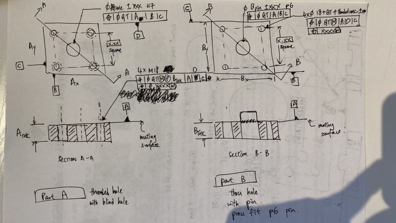
Here's my rationale and assumption for the design part. Sorry for the lousy hand sketch and I may have some detail missed, but feel free to change or correct me if I am wrong:

1. Since mating surface are important, datum A has been chosen as primary datum of BOTH parts, you may also define roughness and flatness as required
2. Datum D will be the center-axis of the hole / threaded hole pattern (Not sure about the priority of datum B,C,D, feel free to change). Here I would also define the threaded hole and clearance hole pattern relative to Datum A|D|C. Also with composite callout to ensure hole pattern follows the center mating feature. For composite tolerance, the top tolerance is the "hole pattern location" relative to the center axis feature (Datum D), the bottom tolerance is the "hole location" relative to each others.
3. In part A, the threaded hole has a projected tolerance value of thickness of (block B + thickness tolerance) to ensure bolt head will clear.
4. for press fit, I assumed p6 pin and H7 Hole (here's what I use ---> 5. I assumed clearance hole in part B "looseness" is not important since press fit pin will guide it anyway, so I use MMC for the clearance bolt hole in part B since MMC purpose is just to make sure the hole will clear the threaded hole in worst case.
 
y2k,
In both of your parts the central hole / pin (the features that have to fit by press) are controlled with reference to datum features A,B,C. If you compare their Virtual Conditions, will they fit?
 
Status
Not open for further replies.

Part and Inventory Search

Sponsor