Continue to Site

Eng-Tips is the largest engineering community on the Internet

Intelligent Work Forums for Engineering Professionals

  • Congratulations IDS on being selected by the Eng-Tips community for having the most helpful posts in the forums last week. Way to Go!

4 Point Bend on an L Shaped Specimen 1

Status
Not open for further replies.

FEAMonkey

Aerospace
Nov 17, 2019
15
Hi Everyone,

My final year project involves modeling a 4 point bending on an L shaped specimen (only elastic). I am new to Abaqus, I have only used Solidworks simulation before. I am using Abaqus 6.14.
I used the instructions provided in this video to set up my FE model:
I had to tweak it a little bit as this video is for 3 point bending test. I also used a rotated CSYS for all of my boundary conditions. I am not really sure where I went wrong. Can someone give me directions or tips?
You can download the model using this link:

or

After submitting my simulation, I received these warning messages:

A transformed coordinate system has been used for node 1 (assembly) which is included in an *equation. However, no active dofs were detected at this node, possibly because the node is not connected to any element. If this situation occurs in an implicit dynamic procedure (*dynamic), it may lead to an inconsitent number of dofs between the fe mesh and the solver and the analysis being terminated. To avoid this situation, please make sure that a point mass and rotary inertia are defined at this node for activating needed translational and rotational dofs.

MPCS (EXTERNAL or INTERNAL, including those generated from rigid body definitions), KINEMATIC COUPLINGS, AND/OR EQUATIONS WILL ACTIVATE ADDITIONAL DEGREES OF FREEDOM

Boundary conditions are specified on inactive dof of 675 nodes. The nodes have been identified in node set WarnNodeBCInactiveDof.

There are 2 unconnected regions in the model.


Your help is much appreciated.

 
Replies continue below

Recommended for you

In Abaqus warnings do not always mean something worrying. Pretty much every complex simulation generates them and most of them can be ignored. But of course it's always recommended to read and understand all warning messages. In your case I think that they don't indicate any serious problem unless the results look incorrect.
 
Could you also attach .inp file ? RF output variable means reaction forces in Abaqus. It will only appear in the regions of the model where boundary conditions are specified. There might be an error in your BCs definition. Personally I would use different approach than shown in the video in this case - try modeling all rollers (including bottom ones) as rigid bodies, assigning all BCs to them and defining contact (pairs or general contact - both should work fine).
 
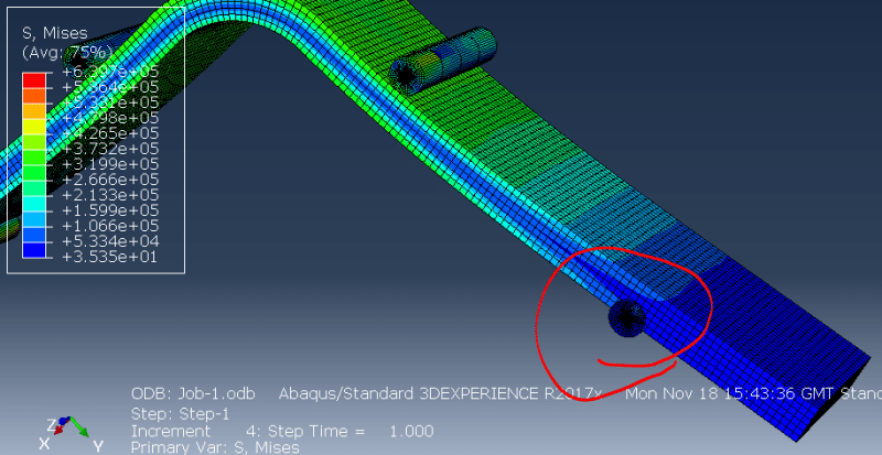
Thank you for your advice, I followed it. I also moved the top two pins down using a boundary condition instead of the reference point method. It seems to work. Although, there is an interesting phenomenon that I don't understand what's causing it. As you can see on this picture, the bottom pin penetrates the specimen but I don't really know why. I used the same interaction settings & properties for all the pins. Any tips on what is causing this penetration? or is this just an incorrect plotting?
Roller_b2wvld.png
 
In the meantime I checked your CAE model. There was an error in the definition of BC driving reference point. It was specified in wrong direction. But after fixing this another problem appeared - pins were penetrating the specimen. I tried various improvements of contact definition and what finally helped was applying small overclosure between each pin and beam and then turning on „Adjust only to remove initial overclosure” option. That’s because the angle between pin and beam was such that it was hard for Abaqus to establish contact. I think that you should try it with your model too. It should work but if the problem still exists try changing contact behavior, adding whole surface of the pin to contact pair definition and changing your model to meet requirements for master and slave surface. Also consider assigning rigid body constraint to the pins.
 
Thank you for your guidance. It is much appreciated. I tried to follow your advice and I couldn't make it work. I used a different approach which seems to give me a better result than I got yesterday. However, the penetration at the lower pins are still present. I tried to assign rigid body constraint on the bottom pins but the simulation got aborted.
I attached my latest setup.
Can someone have a look at my setup and give me advice on this penetration issue?

 
If you use this trick with strain-free ajustment that I described before on your previous model (the one with two pins) and make the pins rigid (using Rigid body constraint) then it should work fine. I did this and got good results. Apart from that I think that it’s better to apply BCs to pins through points like you did before instead assigning them to whole part.
 
Thank you for help. It works fine now :)
I have another question...
How can I export the principal stresses which occurs at each node on the top surface of the specimen?
 
Abaqus calculates stresses at integration points (there they are the most accurate) so you can’t request nodal stresses as history output but they can be interpolated from integration points in postprocessing. There’s more than one way to extract nodal stress values. First create a display group containing only these nodes that you want to evaluate for principal stresses - use Create Display Group, select Nodes as Item and Pick from viewport as Method. Choose by angle and click on the top surface of the beam. Click Done and in the Create Display Group window choose Save Selection As... Then specify a name for this group and confirm. Close the display group creation window. Switch to Plot Undeformed Shape, find Display Groups container in the Results tree on the left, expand it and double click on the name of previously created display group. Use Common Plot Options —> Labels —> Show node symbols to visualize nodes in the selected display group. Now there are two ways to extract stresses from these nodes:
1) use Report —> Field Output, select Unique Nodal, check boxes next to proper principal stress variables and click OK to write them to file
2) use Query —> Probe Values, switch to Nodes, choose Select a display group and pick the one previously created (before doing this you have to select one of the four principal stress variables (max, max(abs), mid or min) so that the probe values tool extracts proper output variable), wait until it collects the data and click Write to File...

The second method is much longer since not only it collects the data slowly node by node but you also have to pick principal stresses one by one. Thus I recommend the first approach.

Apart from this you could also use scripting but in this case it’s not necessary.
 
Status
Not open for further replies.

Part and Inventory Search

Sponsor