Eng-Tips is the largest engineering community on the Internet

Intelligent Work Forums for Engineering Professionals

  • Congratulations waross on being selected by the Tek-Tips community for having the most helpful posts in the forums last week. Way to Go!

4-sided HSS column connection

Status
Not open for further replies.

kruq

Structural
Nov 22, 2017
9
0
0
PL
Hi all,

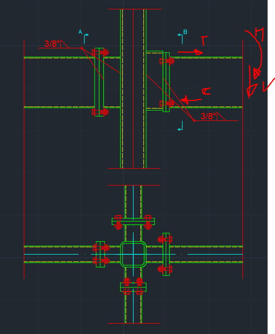
I have question about connection like showed in attachment. I used to work with EC codes so for AISC I need support :) I have two HSS cantilevers attached to HSS 6x6x5/8 column and two HSS beams which are extension for cantilevers to create kind of overhanged beams. On cantilevers there is bending momement 410 kip-in and shear force ~8.5 kip. My first question is can I use in this case 1+0.5sinθ factor for designing welds to column? Because by Chapter K in AISC it is prohibited but I would like to know Your opinion. Second question is do You think differences in outriggers depths will be problematic to transfer bending moments from cantilever to second side? I've checked plastification of HSS wall via chapter K3.2 but I am wondering what can happend on side walls if there are also welded outriggers to post. Thanks for answer.
4-sidedconn_f06lne.png
 
Replies continue below

Recommended for you

Can you use a small length of W6 section and bolt the parts to the flange and weld the opposite flange to the HSS column?

Dik
 
Thanks Dik for answer, but unfortunately I can't use W-flange profile here. But I am just interesting You suggest to make this to avoid concentrated force on flange or for other reason? Clear curiosity :)
 
Krug,

For your first question, I think it's reasonable to prohibit the use of 1+0.5sinθ factor on column face weld, since the faces of HSS won't be stiff enough to provide a uniform stress distribution along the weld length. However, I tried to find this in Chapter K of AISC, both in 2010 and 2016 version, and just can't find it... Could you please provide me the page or anything about this?

Thanks
 
@Zondervan Section K5 in the definition of Fnw, 15th manual page 16.1-158.

Your moment is not very high ~50% stressed I do not see an issue with the HSS transferring the load between the offsets.
 
If you look at a x-section of a HSS 6x6x0.625.. it's a pretty stiff section and the face would not be a concern...

Dik
 
@Zondervan
I thought about this what is described in definition of Fnw like sandman21 said.
@dik
I've checked this plastification and the ratio is something about 40% so you are right it is stiff :) However welds will be the biggest issue. I used to design welds with directional method (von Mises) and with 12" depth outrigger they are too weak, maybe I will use higher outrigger or try "Black Book" tabular method.
 
@sandman21 thank you so much. And I have to say this "no increase in strength due to directionality of load" is so unobvious that even AISC doesn't really want engineers think about it... And the commentary does say this is due to lack of experiment data.

And yeah...HSS6x6x5/8 is pretty thick, but comparing to the in-plain stiffness of the beam top flange, it will be nothing. Then the top flange tension will go to the stiffer part of the HSS column--the two faces that parallel to the beam longitudinal direction, which probably will result in higher stresses at two ends of the fillet weld? But it's definitely better than the longitudinally loaded fillet weld = =... So I guess some kind of directionality increase but smaller than 1+0.5sinθ^2 will be reasonable.
 
The plastification check cover the face design, the OP question was regarding the issue with offset members and if the member would be sufficient to transfer loads.
 
since the face of the HSS col is more flexible than the corners/sides, the majority of the loads will gravitate towards the stiffer elements...in the OP's conn there is just too much going on at the same time and expecting these forces to work their way through the HSS col and having moments in both directions just complicate things further...if one assumes that the majority of the moment is delivered to the col by the sides of the bms , then what happens to the corner of the col with a moment coming in from both directions.....there are better and cleaner(engineering-wise) options available...
 
Hi kruq,

Not at all an answer to your question, but you might find interesting this software:
(there is option to calculate either accord to EC or AISC)

For me it would take ~10min to model and run check on connection like this
For the first time user of course it would take more , but still you would find this very easy to use.

Best Regards
 
I would suggest the same detail as BadgerPE. Break the column, run one beam continuous over the column for one cantilever and the other beam would splice at the cross beam and field weld the column base and cap plates for continuity of the discontinuous beam. Make both beams the same depth.
 
Status
Not open for further replies.
Back
Top