Continue to Site

Eng-Tips is the largest engineering community on the Internet

Intelligent Work Forums for Engineering Professionals

  • Congratulations waross on being selected by the Eng-Tips community for having the most helpful posts in the forums last week. Way to Go!

4 wire rtd with one wire not connected

Status
Not open for further replies.

Yarno

Student
Apr 6, 2021
2
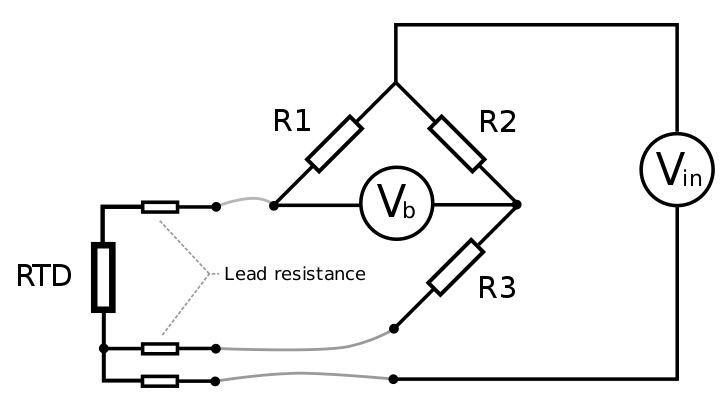
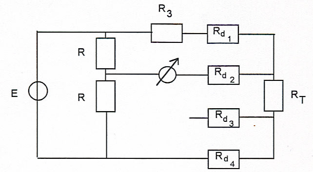
Does anyone know what this type of meassurement does? It's in my electrical engineering class and i can't make anyhting out of it..
It's called a floating point four wire measurement.
A91b0qyg3_1rdxr6k_uo8_t5s3cd.jpg
 
Replies continue below

Recommended for you

Some circuits use three wires.
The third wire is used to cancel out conductor resistance.
Some circuits use four wires for the same thing, cancelling loop conductor resistance.

Bill
--------------------
Ohm's law
Not just a good idea;
It's the LAW!
 
4-wire Kelvin connection is the gold standard for eliminating resistive parasitics from the measurement. 2-wire basically sucks for low-resistance measurements, since contact resistance is often on the order of 0.5 ohm. 3-wire is kind of a compromise, often because someone got lazy in running the 4th wire, or couldn't because of an existing layout.

TTFN (ta ta for now)
I can do absolutely anything. I'm an expert! faq731-376 forum1529 Entire Forum list
 
Ah so it's just the same as a three wire measurement?
And what's up with the name? why do they call it a 'floating point 4wire measurement'?
Why don't they just leave the fourth wire and make it a real 3 wire rtd?
 
The monitoring circuits are different between three wire schemes and four wire schemes.
A four wire RTD gives the flexibility to use either monitoring scheme.

Bill
--------------------
Ohm's law
Not just a good idea;
It's the LAW!
 
A 4-wire configuration is the most precise/accurate, particularly if the RTD or whatever resistor isn't soldered in place, i.e., a switching network or clips are used; the 4th wire allows the parasitic resistances on both sides of the resistor to be eliminated from the measurement

TTFN (ta ta for now)
I can do absolutely anything. I'm an expert! faq731-376 forum1529 Entire Forum list
 
I suspect that if you re-draw your diagram you'll find that the unlabeled R's and R3 form a classic bridge circuit for a 3-wire RTD; and Rd1, Rd2 and Rd4 being the lead resistance.

Compare to the 3-wire RTD circuit from Wikipedia (of all places):

3-wire_RTD_bridge_circuit_cmwksz.jpg
 
Status
Not open for further replies.

Part and Inventory Search

Sponsor