Continue to Site

Eng-Tips is the largest engineering community on the Internet

Intelligent Work Forums for Engineering Professionals

  • Congratulations KootK on being selected by the Eng-Tips community for having the most helpful posts in the forums last week. Way to Go!

40' Pocket Sliding Glass Door 1

Status
Not open for further replies.

Blooongeey

Structural
Jul 3, 2021
20
In my high-end residential applications here by the beaches of southern CA, I typically try to keep deflections of longer spanning floor beams at 0.50" TL maximum. Typical spans I see are around 20 to 26'. I see a lot of these doors, typically 12 - 18' wide, for which I typically tighten the deflections down to 0.25", or less.

A current design in the works calls for a 40' wide door. Loads tributary to the beam are 12' of roof and 15' of floor over the full span. I do not believe 0.25", or even 0.50" is a reasonable limit for this application. The architect has provided approximately 24" for the header depth and the deflection of the header. My initial stab at this resulted in a W18x119, with 1.16"/0.60" TL/LL deflections. I could call out cambering to take out the DL deflection, but am not sure this is necessary, or even achievable.

Any advice would be greatly appreciated,

Michel Blangy, P.E.
Redondo Beach
 
Replies continue below

Recommended for you

I would use a truss, independent from the structure roof or floor loads... there's a price to pay for special features... and make the chord members what they have to be for deflection... and camber if necessary.

Rather than think climate change and the corona virus as science, think of it as the wrath of God. Feel any better?

-Dik
 
It sounds like a Nanawall. When I have designed openings for these in the past, the manufacturer was able to provide the amount of deflection that their product could accommodate.
 
I agree with dik. You have a very unusual circumstance and it will require greater than usual structure members/details to make it happen. Unfortunately the door is going to have strict deflection limits, regardless of how 'reasonable' they may or may not be.

You also need to talk to the architect - 24" is a bit shallow for that long of a span and an application requiring tighter than 'line-of-site' deflection.
 
some sections and a plan would help you get some feedback/ideas, I think. Rather than tell you, "use a heavier beam," there may be other approaches that get you to a solution:

-add framing to reduce the tributary width?
-do something different at the roof to eliminate the roof load on the beam?
-create a vierendeel truss with the top chord at the roof?
-put posts in that will work even though the architect claims they won't?
-create a sliding detail at the top of the window to allow for deflection?
-add some posts inside the space and cantilever the upper framing perpendicular to the sliding wall
 
-add framing to reduce the tributary width?
you want no tributary width... has to be totally independent.

-do something different at the roof to eliminate the roof load on the beam?
See above...

-create a vierendeel truss with the top chord at the roof?
Vierendeel truss is not stiff enough... you want HSS top and bottom chords and angle web members or maybe HSS vert web members. You want no flexibility at the panel points.

-put posts in that will work even though the architect claims they won't?
posts can help reduce deflection if you can...

-create a sliding detail at the top of the window to allow for deflection?
that can help if you can do it...

-add some posts inside the space and cantilever the upper framing perpendicular to the sliding wall
making the end supports rigid, not using a pinned type connection can minimise deflection.

[Added] 40' with limited dead load and a 24" deep truss with wide rectangular sections to maximise effective depth, and a load you are certain of, is doable...d(in)/L(ft)= 0.6, minimum, but OK. Camber for Dead Load...[Added]

Rather than think climate change and the corona virus as science, think of it as the wrath of God. Feel any better?

-Dik
 
Not sure how seismic or wind affects this but you need a bunch of out-of-plane capacity for a 40 ft. run.
Your jambs are taking a pretty big in./out load and so is the weak axis of your header.
 
I would like to reply to the various replies, but do not know how to quote a previous post?
 
Look for the icon with the person with the quote bubble. 7 buttons over from "Submit Post"
 
right below the "e" in Signature. It's a multi-step process if you want the full monte
> copy/paste the stuff you want to be quoted into the dialog box
> copy the source's handle/name
> select the quoted text in the dialog box
> click the quote icon and paste/type the handle or name in the "who?" dialog
> click OK
icon_gbfn28.png


TTFN (ta ta for now)
I can do absolutely anything. I'm an expert! faq731-376 forum1529 Entire Forum list
 
Typically the door manufacturers have deflection criteria required for their doors, for instance, I just pulled up a NanaWall owner manual for one of their doors and the limit is the lesser of L/720 and 1/4" for dead+live. Normally the 1/4" is what I see and use for many similar cases. Have you tried an HSS member? I have successfully gotten these to work in the past. I'm not sure what your structure is, but maybe a W24 could fit with sheathing attached directly to the steel member, not ideal but doable. Is there a way to rotate your framing to have less loading on this header? Can the architect work with a double sliding door with a column in the middle (most likely not, but can ask)? If you can get a WF beam to work vertically, for horizontal loading you can brace to diaphragm, add a channel or something sim to make it work, none of which are ideal for a header unless you can hide the framing. I assume since you say they only gave you 24" header space, then your floor/roof framing ties directly into the beam and therefore you may be able to hide bracing the beam to the diaphragm in the floor/roof framing. If the header is dropped and it's 24" to bottom of roof/floor framing, maybe you can side mount to the header and extend the header taller? Can you provide a sketch of what you have?
 
Rather than trying to find a shop that can camber the beam 'the hard way', you could consider using a plate girder. The camber is 'designed in', and the you can vary the plate dimensions to limit LL deflection to whatever you need. Same with the vertical strength and lateral strength.

Rod Smith, P.E., The artist formerly known as HotRod10
 
HouseBoy said:
They came up with this test (see pic):

I suppose that would work. Seems unnecessary for a steel beam, in particular, unless they were counting on other components for part of the resistance - moment of inertia should be easy to calculate, and the modulus of elasticity for steel is well established and falls within a narrow range. I could see that being useful for a wood beam or truss, though.

Rod Smith, P.E., The artist formerly known as HotRod10
 
I am sure why you have to test the beam in that case. Almost all the dead loads were in already (except roofing I believe). Whatever deflection due to the actual dead load could be corrected by the bottom nailer. Test for the roof live load deflection? You won't see any significant roof live load that can cause serious deflection of the beam ever.

What did that test load (piles of blocks) represent? Dead load? Dead + Roof live?

To OP: I don't see anything wrong with cambering the beam that long. It's the way to do get the economical size. For deflection due to live load, that beam can have a big live load reduction (almost 30% so maybe you took that into consideration). Also at the same time for residential you don't see any actual live load of more than 20psf. I would feel comfortable with 1/2" LL deflection knowing that in reality, it won't be more than 1/4". All deflection due to dead load + camber if any can be corrected with nailer or shim at the bottom of the beam.
 
As others have said I would reduce the tributary to the beam. Or you could put in a moment frame at that location to reduce deflection with some added stiffness from the fixity at the ends.

I would look up the deflection criteria from the door manufacturer and make sure you meet their requirements. A 40' door like that costs over $50k. You don't want an issue with it. If you can't meet the deflection requirements that's the architect's problem (after all you are not a magician) and they need to revise their design if there are no other structural options.
 
This is going to be sloppy post. I'd not bother but I really do feel that I may have some insight to offer and I don't have time to clean it up. The quote below is taken from an email that a friend sent to me after finally managing to speak with a sympathetic manufacturer's rep who knew his stuff.

In many cases, I feel that the practical answer is to be very aggressive, both in terms of the loads used to calculate the deflections and the amount of deflection that is permissible. The clip below covers the permissible deflection well. In a place like California, where you probably have no meaningful snow to deal with, what really are your loads? Consider that:

1) It's quite reasonable to ask for the sliding door to be installed after most of the instantaneous dead load is in place.

2) Your 20 PSF roof live load probably represents a construction case. What are the odds that load is applied over the full tributary area or that anyone really needs to open the door while construction is underway?

3) Downward wind forces, if you even bother to consider them, probably represent another point in time where sliding door performance is not critical. Is it really a problem if your sliding door sticks once every 10 years when the design wind storm is occurring? Perhaps, if you're trying to get inside for shelter. Or outside because the roof is coming down.

4) If there is a floor above, is it really going to see 40 PSF? Statistically, it's unlikely to even see 10 PSF I believe.

5) Realistically, plausible "failure" is probably just the breaking of the glass and getting sued over that. Per the quote below, it may take a fair bit of movement to generate that outcome.

6) From what I've seen of other people's designs, a lot of folks must be taking a fairly liberal approach. Short of incompetence / ignorance, there's just not no other way the stuff that's out there works.

KootK Friend said:
For these particular doors I'll have on PR they state 1/8" max deflection. When I went through what this joint actually looks like it turns out that it's a 5/8" flexible joint, 3/16" of which is taken up by the door lifting on its rollers so in reality there is 7/16" theoretically before you bottom out. He confirmed that this is correct but said that due to the brush and rubber gaskets you'd get a lot of resistance before then, so he said maybe 3/16" to 1/4" movement in reality before you have problems operating it but you'd still be safe from it exploding on you. During the install there are jack screws which are 1/2" at their max (and they do offer 5/8" versions).

If you can get the contractor to prep the r.o. such that the door installs with the 1/2" already maxed out it means that in the future they can be backed off up to 1/2" without removing anything (they are accessible behind some caps in the head track and turned with an allen wrench). So in a best case scenario - you've got about an initial 1/4" to play with (vs their stated 1/8"), at which time you could tune the door another 1/2" if needed. So up to about 3/4" before you've used up your 1/2" shim screws + wiggle room and start binding again. He said that if you hit that point they then have to pull the head and dig our material etc. to reset. So long story short it seems like if some future tuning is accounted for it's not so terrible.
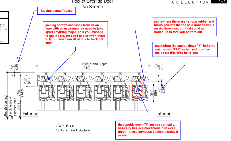
c01_oxy95u.png
 
Status
Not open for further replies.

Part and Inventory Search

Sponsor