Continue to Site

Eng-Tips is the largest engineering community on the Internet

Intelligent Work Forums for Engineering Professionals

  • Congratulations KootK on being selected by the Eng-Tips community for having the most helpful posts in the forums last week. Way to Go!

46-4 DESIGN BY ANALYSIS ASME BPVC.VIII.1 2

Status
Not open for further replies.

tigny

Structural
Mar 12, 2001
108

Hi,

for an ASME BPVC.VIII.1 "Design By Rule" designed pressure vessel, we conduct a supplemental analysis along the requirements of Appendix 46, 46-4 DESIGN BY ANALYSIS (using the methods of ASME BPVC.VIII.2 Part 5).

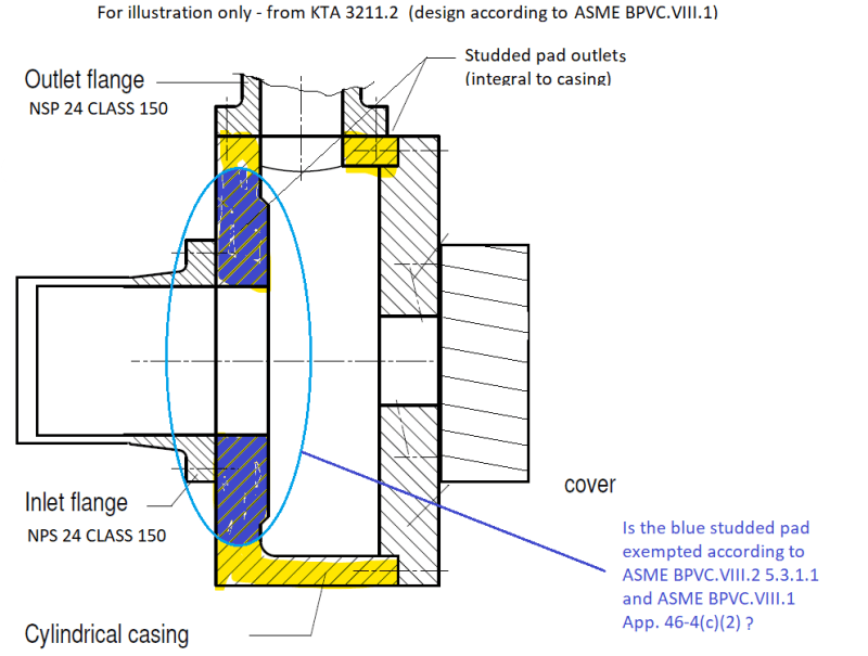
One of the components of the numerical model is a Studded pad type connection designed to Div. 1 Subsection A General Requirements PART UG (i.e. UG-43(d), ...). It is not of welded construction (it is integral to the pressure vessel).

As for 5.3 PROTECTION AGAINST LOCAL FAILURE, Div.2 5.3.1.1 states "[...] These requirements apply to all components where the thickness and configuration of the component are established by using design-by-analysis rules. It is not necessary to evaluate protection against local failure (5.3), if the component design is in accordance with Part 4 (e.g., component wall thickness and weld detail per 4.2)."

Div.1 APPENDIX 46-4(c)(2) requests "[...] The exemption provided in Division 2, 5.3.1.1 is applicable to weld details in Division 2, Part 4 only. There exist weld details in Division 1 that are not permitted in Division 2 [subject to the provision in 46-3(f)]; those details are not exempt from evaluation of protection against local failure.".

[ul]
[li]Could this mean that, of all components, only welds are exempted; or that same exemptions apply, except for Div.1 weld details which are not covered in Div.2?
[/li]
[/ul]
best regards,

Cyril
 
Replies continue below

Recommended for you

Best is a drawing, and more info: material, design pressure and temperature.......etc.

Regards
 
I agree that a drawing would be best to assist you. However, if you are choosing the design thickness of a component using Appendix 46-4 because there are no rules in VIII-1, then you component detail is likely not exempt.
 
Dear @r6155, dear TGS4,

thank you for interest in my question and your replies.

I indeed did not and do not intend to design the thickness with DbA. The dimensions have been assessed with UG of Div.1. The DbA is done as a supplement to the DbR.

The DbA run is not to assess this particular component (studded pad outlet); this component is present in the numerical model in order to obtain correct limit conditions for the rest of the model.

Here is a simplified representation of the location of the component in the complete model:

representation_of_numerical_model_eqxoxj.png
 
Ummm....
Lateral view?
General dimensions, material, design pressure & temp. ?

Regards
 
You 'sketch' makes your problem as clear as mud.
It barely looks like a Pressure Vessel.
 
I would treat this similar to a pad flange, where the blue area is a reverse loose flange (or maybe a reverse integral in this case) per VIII-1 Appendix 2, then check the holes to UG-43(d) and (g). I would also do an area replacement check on the opening and limit the radius so it doesn't go into the tapered section, also remove area for the tapped holes. That keeps you in VIII-1.

However, with the flange connection on the top of the picture, I'd say just do an FEA.
 
To answer the OP's original question about whether this component would be considered a "standard" component and therefore be exempt from evaluation of Protection Against Local Failure - my answer would be no.
 
@ tigny.
Are you there?
I suggest follow KTA 3211 Safety Satandard of the Nuclear Safety Standards Commission (KTA), step by step,

Regards
 
Dear r6155, DriveMeNuts, Cobra17, TGS4,

thank you for your interaction, answers and questioning.

Our design follows the ASME BPVC.VIII.1 design by rule calculations, taking into account the Reverse flange (Appendix 2), Opening (mainly UG-36, UG-37, UG-40 (fig UG-40 (a-2)) and Method of attachement of pipes and nozzle necks to vessel walls UG-43(d) Studded Connections, and (g) Tapped holes engagement length rules.

We do the FEA calculation mainly for the top opening, when we cannot move it away from the main body flange.

[ul]
[li]However, because of this sentence "The exemption provided in Division 2, 5.3.1.1 is applicable to weld details in Division 2, Part 4 only" my main question is still to know if, of all components, only welds are exempted; or if the same exemptions apply, except for Div.1 weld details which are not covered in Div.2? [I am not a native english speaker][/li]
[/ul]

@r6155, I'm all right, thank you for inquiring [bigsmile]. As I mentionned on the drawing, the illustration is for illustration only, I used it so that eveyone can have a glimpse of the general geometry of the design. We are not working for nuclear/atomic indsutry.

tigny
 
DriveMeNuts said:
It barely looks like a Pressure Vessel.

Being a machinery housing, but pressure being the driving force for the dimensions, we prefer to use a pressure vessel code to design it.
 
5.3.1 Stated that it is not necessary to evaluate protection against local failure, if the component design is in accordance with Part 4 (of ASME VIII-2).
It is my opinion that if your component is design in accordance with ASME VIII-1 than you are not exempt from local failure assessment in ASME VIII-2, 5.3.
 
Dear IdanPV
IdanPV said:
5.3.1 Stated that it is not necessary to evaluate protection against local failure, if the component design is in accordance with Part 4 (of ASME VIII-2).
It is my opinion that if your component is design in accordance with ASME VIII-1 than you are not exempt from local failure assessment in ASME VIII-2, 5.3.

Thank you. I understand your interpretation, so the answer to my initial question would be: there is no exception for VIII.1 components, furthermore for VIII.1 weld details not permitted in VIII.2.

So 46-4(c)(2) could be rewritten as "demonstration of protection against local failure shall be done on all VIII.1 components without exception"?

I suppose it was not the intent of this paragraph. [ponder]

best regards

tigny
 
That was most definitely not the purpose of the paragraph. The exemption permitted in 5.3.1 is for standard components and standard details contained in Division 2. But there are details (particularly weld details) that exist in Division 1 that are not permitted in Division 2. These are often referred to as the "crappy" details. Most Oil and Gas companies (especially the majors) do not permit these details on the vessels on their sites. They typically contain un-inspectable features or features that might cause crevice corrosion, or similar degradation mechanisms. Thos edetails do not exist in Division 2. Plus, there is some uncertainty whether those details would provide an adequate margin against local failure.

I certainly object to the interpretation that IdanPV offers. That was not my intention, at all, when I wrote that paragraph in 46-4. And that was confirmed by other members of the Code Committee.

Nevertheless, it is not required to exempt a component from evaluation of this failure mode. It is certainly my standard practice to evaluate this failure mode every time.
 
TSG4,
It seems that there is a conflict between 46-4(c) and 5.3.1.
Because 5.3.1 Stated that it is not necessary to evaluate protection against local failure, if the component design is in accordance with Part 4 (of ASME VIII-2).

When one perform FEA in accordance U-2(g) and Mandatory Appendix 46, he design it in accrodance with ASME VIII-1 so, how it can be exampted from evaluate protection against local failure?
 
If the design details match, then you’re fine and the exemption is acceptable. But as I said earlier, there are poor details acceptable to VIII-1 that are not in VIII-2. Those details are not exempted.
 
@ tigny
You are in problems when mixing codes/standards.
KTA 3211 is clear (use in nuclear or not).

Regards
 
Dear @r6155,

I greatly appreciate your concern, however I will restate that this illustration if for your information only:
I don't want to disclose my company's drawings therefore I used this image because the general arrangement of the components is the same.​

I don't want to mix codes; as you may have noticed, that is the purpose of this thread, in which I asked about the wording of ASME BPVC.VIII.1 MANDATORY APPENDIX 46 RULES FOR USE OF SECTION VIII, DIVISION 2, 46-4 DESIGN BY ANALYSIS with regard to ASME BPVC.VIII.1 CHAPTER 5.

best regards,

tigny
 
I assume your design has no welding, right?

Regards
 
TGS4 said:
But there are details (particularly weld details)

Dear TGS4,

May I try to sum-up my understanding: the wording "[...] The exemption provided in Division 2, 5.3.1.1 is applicable to weld details in Division 2, Part 4 only. There exist weld details in Division 1 that are not permitted in Division 2 [subject to the provision in 46-3(f)]; those details are not exempt from evaluation of protection against local failure." is now clearer to me:

[ul]
[li]For a DBA analysis according to ASME BPVC.VIII.1 MANDATORY APPENDIX 46, 46-4(c)(2), only welded components with DIVISION 2 acceptable welds details may be exempted according to Division 2, 5.3.1.1. There are no other exemptions.[/li]
[/ul]

best regards,

tigny
 
Status
Not open for further replies.

Part and Inventory Search

Sponsor