Continue to Site

Eng-Tips is the largest engineering community on the Internet

Intelligent Work Forums for Engineering Professionals

  • Congratulations KootK on being selected by the Eng-Tips community for having the most helpful posts in the forums last week. Way to Go!

50 ft long truss beam with a 300 kip point load 4

Status
Not open for further replies.

davab

Structural
Sep 22, 2012
35
Hi guys,

I am designing a 50 feet long steel girder that has one point load that is around 300 kips. This resulted in a huge steel beam that is W40x372. Due to cost implications, we are considering to design a truss beam at that location. I have been using RISA to analyze this truss member and I am not able to optimize the steel tonnage as much as our team expects. I have looked into every possible resources to figure out whether something is wrong with my model. I can't seem to find anything wrong with the boundary conditions or the model setup.

Here are some general info:

Top and bottom chords are continuous Wide Flange.
Diagonal and vertical members are "pinned" to take only axial loads and each bay is spaced at 5 feet o/c.

Note that the top and bottom chords are modeled continuously, which is more realistic representation of a real life truss.

Contrary to what I was expecting for a truss, I am getting a huge moment at the top chord. I believe that it is resulted from "secondary moment" that is being created by a huge point load.

My question is:

1. Has anyone modeled a truss that had a substantially asymmetric point load? (meaning that 300 kips is located at one side only and not symmetrically)
2. Does anyone know if trusses are not economical when handling such asymmetric loading?

Any thoughts or concerns would be helpful.

Thanks guys.

 
Replies continue below

Recommended for you

Is the point load applied at a diagonal connection point to the top chord?

Are you getting the expected axial forces in the diagonals and verticals and what are you getting in the the bottom chord?
 
Which way are your chords oriented? Turning the chords so the webs are horizontal makes them act more like a truss, and lessens the requirement to brace the chords.
 
Trussing should be an effective strategy for your situation. I'd like to know a little more:

1) Where on the span is the point load located?

2) Is the point load located at a panel point as one would expect?

3) parallel chord truss shape or something else?

4) What size, shape, and orientation of chord is being used?

5) Linear elastic modelling so far?

6) How deep is your truss?

My guess is that your truss is simply not deep enough. Any parallel chord truss with continuous chords will have the following three mechanisms acting concurrently and drawing load in proportion to their relative stiffness:

1) Top chord acting as a beam.
2) Bottom chord acting as a beam.
3) Truss acting as a beam.

If three isn't substantially stiffer than one and two, you'll get beam-ish results in the chords (moments and shears). Check the vertical shears in your chords near your supports and add them together. That's about how much load is not going through your truss, acting like a truss.


I like to debate structural engineering theory -- a lot. If I challenge you on something, know that I'm doing so because I respect your opinion enough to either change it or adopt it.
 
Can you avoid the eccentric 300K load? A huge force for a trussed assembly. Can you use a double truss with the load centred between?

Dik
 
rapt: I am getting expected axial loads at both top and bottom chords. With the depth 5 feet deep and each Bay 5 ft wide, my diagonals are pinned at 45 degrees, which is an ideal angle. So yes, all of the axial load dumps into the diagonal and goes straight back to the support since the load is only 10 ft away.

hokie66: I have the chords oriented in strong axis. You are onto something here because I tried to play with different chord members. When I made them more flexible, I was able to reduce the sizes and the moment went down at both chords. Unfortunately, this resulted in L/180 which isn't good enough. To get the deflection limit to L/360, I needed stiffer member, i.e. wide flange, and it increased the moment somehow. As a result, my combined axial and bending check exceeded unity as my bending demand went up while axial load demand was relatively similar for either member choices.

Hope this clarifies a little. Thanks.
 
Local strength of the member taking the 300kips may be an consideration you put first.
 
you need sufficient steel area to control deflection. Keeping the chords laid horizontally (if W shapes) is definitely the way to go. A trusses deflections is primarily controlled by the area of the chords, its MOI is basically A*(d/2)^2 with A the chord area and d being depth of the truss. If you want to reduce steel weight, increasing depth is the only way to go, as you will always need a good amount of steel area to resist the chord axial loads.
 
KootK:

1) Where on the span is the point load located? 50 ft span and point load is at 40 ft. (we have 10 feet on the other side (2 bays) that can fit 2 diagonals to reach to the support at the right)

2) Is the point load located at a panel point as one would expect? It is located at where the diagonal is.

3) parallel chord truss shape or something else? Truss looks like this. Assume that the angles are actually HSS members.
4) What size, shape, and orientation of chord is being used? W18x87 at top and bottom chords. HSS8x8 at diagonal where the point load applied and smaller HSS at other locations where there are no point loads.

5) Linear elastic modelling so far? I am using reduced stiffness option in RISA that is adjusting stiffness iteratively.

6) How deep is your truss? Truss is 5 feet deep.
 
for truss members, when using W as the chords laid flat, if I can get a similar depth, but light W shape for the web members, it can allow for flanges side gussets to be attached and bolted with spacer plates to the chords as required. It makes fabrication and fit up go fairly smooth.
 
Pay close attention to lateral bracing for the truss at top and bottom chord. Also consider cambering the truss if serviceability is a concern
 
If making the combined checks on the chords work is the name of the game, another thing to explore might be your chord bracing assumptions.

Another thing to play with is your web sizes. Up the sizes well beyond that required for strength and see if that makes a difference. Sometime, if webs are strong enough but not very stiff, you'll get high shear deflection across the truss that will draw more moment to the chords. I wonder about it here because, with that monster load only 20% from the support, I'd expect your truss response to be dominated by shear more than flexure.

I like to debate structural engineering theory -- a lot. If I challenge you on something, know that I'm doing so because I respect your opinion enough to either change it or adopt it.
 
And all of the webs are modelled meetimg up comcentricslly with each othe at the chord centroid?

If you're top chord hung, is that where the big moments are showing up?

How about a screen capture of the truss with it's moments plotted?

I like to debate structural engineering theory -- a lot. If I challenge you on something, know that I'm doing so because I respect your opinion enough to either change it or adopt it.
 
It might be worth taking a step back and reminding yourself that you are putting a 300k point load on a 50' span. There's only so much "optimization" you're going to be able to accomplish.
 
Not that this will be helpful, but I had a slightly similar situation come up recently on a column removal. While the client hasn't give the go ahead yet on the project he is still talking. In this instance it was an 90k load on a truss that was 80' long. In this I sized a WF beam and then told the client to get a price on a 96G2N90k girder from a manufacturer (depth wasn't too big of an issue). Don't know if this would work for you or not.
 
My gut says it's going to be difficult to find enough weight savings in 20" of additional depth to justify the labor involved with fabricating the truss. But my gut is often wrong and I'm curious how this will play out. Please keep us updated.
 
An old guy once told me that if you estimate the truss height in inches to be equal to the span in feet then it will be economical. Yours is 50 feet -> 50 inches and your truss is 5 feet = 60" tall. So by that measure it should be more economical than a single beam. That said, a center point load is a more extreme load than what trusses usually are used for. You may be in the world of can be done but is not going to save you much money. I'll be following your progress!
 
azcats and IFRs...I would have thought for savings, the least costly configuration for the 300K loading would be 8' or so deep for that span... not at all a uniform loading condition. For typical roof framing a 50' span would usually use 0.7*50 =35, so I'd typically use 36" deep LSSJ...

Dik
 
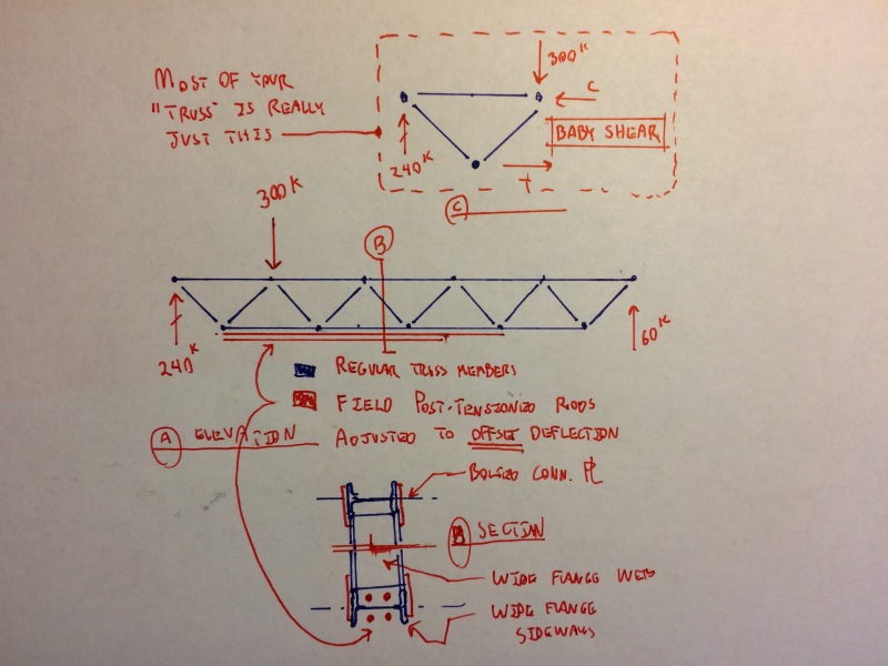
I've proposed an idea below that may have merit given the nature and scale of what you're doing.

- give consideration the the possibility that it may only be the deflection immediately below the 300 kip load that matters here rather than the midspan truss deflection.

- I've suggested post-tensioning the bottom chord. The big advantage of that is that you can tune the tensioning rods in the field to drive the truss upwards and offset the deflection which seems to governing your design. That may get you some meaningful efficiency improvements.

- You'd have some extra compression in your top chord of course but also less bending.

- In terms of pure material quantities, it would probably be more efficient to harp the post tensioned rods up towards the supports. Doing so would probably introduce some costly connections at the direction change, however. Doing the straight PT shouldn't add all that much fabrication cost. Some erection cost though.

- Like my colleagues here, I'm a big fan of the weak axis WF chords. In addition to the praises already sung, it might facilitate the easy delivery of the monster load into into the truss. If you're interested in taking it that far, let me know and I'll elaborate.

- Considering clearances, it may be more constructable to put the tensioned rids outboard of the bottom chord flanges. I'll leave that decision in your capable hands.

IMG_4941_dtgx5f.jpg


I like to debate structural engineering theory -- a lot. If I challenge you on something, know that I'm doing so because I respect your opinion enough to either change it or adopt it.
 
Try the economics (and functional) advantages of two close trusses 12 to 6 inches (or even as little as 3 inches) apart, with the two braced against each other. Seems the lod then (in each truess) is "only" 150,000 pounds, and you get the load suspended between the two with more-or-less automaticanti-sway bracing already available, and less secondary load and building interferences than a single huge WF beam.
 
Status
Not open for further replies.

Part and Inventory Search

Sponsor