Continue to Site

Eng-Tips is the largest engineering community on the Internet

Intelligent Work Forums for Engineering Professionals

  • Congratulations IDS on being selected by the Eng-Tips community for having the most helpful posts in the forums last week. Way to Go!

Truss or not a Truss?

Michel60

Structural
Aug 7, 2012
117
I've lurked around the site for a number of years now, offering my $0.02 occasionally (maybe two-bits with inflation and tariff). I now have a question for the group about a proposed truss profile for a residential project where my first reaction is a "hell no", see below. Its 45' long with a maximum depth slightly over 3'-4". To be fair to the truss designer they were asked by the client (without consulting me first, I was assuming that the area would be stick framed) to generate a budget so this is still a fictitious design right now to get to a preliminary cost. The "special trusses" are for a low-slope (<1:12) membrane roof, but the "girder trusses" support about an additional 12' tributary of a 3.5:12 slate roof.

So far I've only seen the profile summary, no calcs. But even with calcs saying it works I'm not inclined to accept the results. I can't imagine that typical truss design software can really handle this problem reliably. I know some of the regulars here have a pretty strong background in plate truss design so my questions to them are:
1) Do you see this as a legitimate truss profile (either typical or girder)?
2) If you do, can the common truss programs out there adequately design something like this?

Thanks!
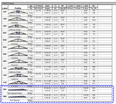

1744399929276.png
 
Replies continue below

Recommended for you

I agree, even at the 4 plys, it looks inadequate. Seeing the calcs would be a must.
 
Both of the selected designs appear much too shallow, but they should be checked by calculation, taking into account the actual dead and live load.
Truss programs used by fabricators should be capable of providing a reliable answer.
 
1) Do you see this as a legitimate truss profile (either typical or girder)?

It certainly raises my hackles a bit. I would like to see the layout that includes these trusses.

2) If you do, can the common truss programs out there adequately design something like this?

Sort of? In these situations, a check of the design drawing usually does indicate that everything is fine. Analytically, the software is fairly bulletproof.

The trouble, in my mind, arises with the fabricator's -- or anyone's -- ability to manufacture such a truss in accordance with the drawings and tolerance limitations. I have a bit of an edge in this department in that I've built a lot of prefab trusses, including some very aggressive ones like this. Here's what I see:

1) I think that everything looks fine on the right 2/3 of the span.

2) On the left 1/3 of the span, the webbing gets so congested that it's practically solid lumber. This creates the following problems:

a) Gaps between members that are trivial in normally proportioned trusses will get uncomfortably large. Very shallow web cuts are tough to do accurately at the saw.

b) Plating will require very large plates that are often very sensitive to accurate placement for their performance.

c) Truss software uses modelling algorithms that are more product specific and less obvious than your typical EOR FEM model. Member centerlines won't actually be on member centerlines, joints will be pseudo modelled to capture eccentricity, etc. The more congested things get, the less valid this model is likely to become.

Vetoing a truss that works according to the software takes some persuasion and finesse. Use the arguments above for the purpose.
 
There's no way to make an intelligent assessment based on those tiny little pictures.

The OP said: "I can't imagine that typical truss design software can really handle this problem reliably."

That's utterly ridiculous. Designing trusses is what the software was made to do.

Two suggestions come to mind. One is to ask for an "in house" truss drawing. (Unsealed) That will give you a much better idea what the actual truss design looks like.

Second is to check total deflection. Ratios are unhelpful in situations like this.
 
It certainly raises my hackles a bit. I would like to see the layout that includes these trusses.


Sort of? In these situations, a check of the design drawing usually does indicate that everything is fine. Analytically, the software is fairly bulletproof.

The trouble, in my mind, arises with the fabricator's -- or anyone's -- ability to manufacture such a truss in accordance with the drawings and tolerance limitations. I have a bit of an edge in this department in that I've built a lot of prefab trusses, including some very aggressive ones like this. Here's what I see:

1) I think that everything looks fine on the right 2/3 of the span.

2) On the left 1/3 of the span, the webbing gets so congested that it's practically solid lumber. This creates the following problems:

a) Gaps between members that are trivial in normally proportioned trusses will get uncomfortably large. Very shallow web cuts are tough to do accurately at the saw.

b) Plating will require very large plates that are often very sensitive to accurate placement for their performance.

c) Truss software uses modelling algorithms that are more product specific and less obvious than your typical EOR FEM model. Member centerlines won't actually be on member centerlines, joints will be pseudo modelled to capture eccentricity, etc. The more congested things get, the less valid this model is likely to become.

Vetoing a truss that works according to the software takes some persuasion and finesse. Use the arguments above for the purpose.
Very useful, just the kind of insight I needed. Thanks KootK.
 
There's no way to make an intelligent assessment based on those tiny little pictures.

The OP said: "I can't imagine that typical truss design software can really handle this problem reliably."

That's utterly ridiculous. Designing trusses is what the software was made to do.

Two suggestions come to mind. One is to ask for an "in house" truss drawing. (Unsealed) That will give you a much better idea what the actual truss design looks like.

Second is to check total deflection. Ratios are unhelpful in situations like this.
I do appreciate the imagines are inadequate but they are what I have at the moment. Ultimately there well be a full design package produced and the suppliers that I work with are usually very good about getting me a pre-stamp version to review. This one just came in out of the blue when I had barley started looking at the possible layout and loading. Seeing that profile triggered that I needed a bit more background support here. My concern with software capability is based on my own limited knowledge of what underlying assumptions for geometry, member type definition, etc. that are baked into them. But hearing that they can potentially analytically address the problem is helpful. Now I just need to get that analysis married with the reality KootK describes and we'll see where that leads me.

Thanks Ron.
 

Part and Inventory Search

Sponsor