Continue to Site

Eng-Tips is the largest engineering community on the Internet

Intelligent Work Forums for Engineering Professionals

  • Congratulations SDETERS on being selected by the Eng-Tips community for having the most helpful posts in the forums last week. Way to Go!

interior truss heel sheathing

struct_eeyore

Structural
Feb 21, 2017
264
I have a series of wood trusses terminating on the interior of the building which have some very tall heels (13'+)
There is no shear transfer by design here - although some might occur in reality.
I'm leaning towards sheathing this section full height, but am wondering if that might be overkill - in lieu of X-bracing.
(truss profile is hatched in figure below)
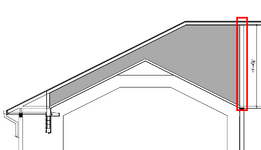
Screenshot 2025-03-24 152157.png
 
Replies continue below

Recommended for you

KootK said:
Like this??

Something like that, yes. With a tall heel the likelihood of imperfections are much higher - from the lumber itself (dimensional lumber isn't looking so hot these days) to tolerances in the construction that could result in some twisting of the cross section. This is why the moment arm between points of lateral restraint at the roof diaphragm and top plates doesn't give me ease and I think is rather irrelevant. I don't think the reason we provide explicit rotational restraint in conventional framing is because the moment arm between points of lateral restraint at the top/bottom is insufficient.

As previously mentioned though, I think there are more efficient solutions than just sheathing the entire heel.
 
Creating a sheathed wall out of this seems excessive to me, but adding 2x4 diagonal bracing seems like a no brainer. Just do it.
 
Something like that, yes. With a tall heel the likelihood of imperfections are much higher - from the lumber itself (dimensional lumber isn't looking so hot these days) to tolerances in the construction that could result in some twisting of the cross section.

I disagree. The angular displacement between the chords and the webs will be so small as to create an utterly trivial demand for rotational stability. The extent that the truss will remain plane but be installed out of plumb will create a vastly more significant rotational demand and even that will be miniscule. It's not as though you're going to accept this 13' tall truss being even 2" out of plumb.

This is why the moment arm between points of lateral restraint at the roof diaphragm and top plates doesn't give me ease and I think is rather irrelevant.

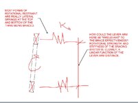
See the sketch below demonstrating the relevance of the bracing lever arm. Given that the brace effectiveness will vary in linear proportion to the lever arm, I would argue that there is no single variable that is more relevant.

I don't think the reason we provide explicit rotational restraint in conventional framing is because the moment arm between points of lateral restraint at the top/bottom is insufficient.

Consider two scenarios with the same end reaction.

1) A 2x10.

2) A 10' tall truss.

Per the sketch below, both setups have the same springs more or less, right? A sheathed diaphragm up top and a nominal shear wall or whatever below. The only difference is the lever arm.

Since the springs are the same, this means that the rotational strength and stiffness provided to the 2x10 is the lesser because of it's reduce lever arm.

The two systems only remain equivalent with respect to rotational stability if the out of plumb-ness of the truss is the same as that of the 2x10. This would cause the P-delta rollover tendency of the truss to grow in the same, linear proportion that the brace effectiveness grows.

But, then, how realistic is that? Consider:

- a 2x10 at 5% out of plumb will be shifted 0.5" across its depth.

- a 10' truss at 5% out of plumb will be shifted 6" across its depth!

And there in lies the difference between deep and shallow setups. A 1/2" on the 2x10 is conceivable. 6" on the truss is not. Or at the least, at 6" the engineer has recourse to say that the truss is well out of tolerance and, therefore, any associated problems are not the engineer's responsibility.c01.JPG
 
Last edited:
@KootK, imagine a 1" diameter wooden dowel that is 1" long oriented as a vertical, freestanding, column with a 10 lb load placed at the top. Now imagine the same setup with a 1 ft long dowel and a with a 10 ft long dowel. Imagine that all 3 dowel columns are perfectly straight and plumb, but the loads may be placed eccentrically and may not act colinearly with the axis of the column. Are these systems equally likely to remain stable or become unstable? If not, which of these systems is most likely to become unstable and why? Isn't the tallest dowel/column most likely to become unstable? Why? For any given colinear eccentricity due to load placement, the magnitude of overturning moment and the resistance to overturning will be the same for all three systems. However, for any given direction of action that is not colinear with the axis of the column, the taller the column, the greater the magnitude of overturning moment induced, and the greater the magnitude of resisting moment required to maintain stability.

Doesn't the above system apply to planar joists and trusses and suggest that taller/deeper joists and/or trusses are more likely to rollover than shorter/shallower ones?
 
@KootK, imagine...

Thanks for this. I'm having the kind of day that can only be made more fun with a mental experiment.

Are these systems equally likely to remain stable or become unstable? If not, which of these systems is most likely to become unstable and why? Isn't the tallest dowel/column most likely to become unstable? Why?

It depends on the type of "stability" being evaluated. For Euler-esque buckling between the ends of the dowels, the taller dowels are obviously more prone to buckling. And the "why" is just the impact of that [L^2] term in the equation for Euler buckling.

But the question here is not about that kind of stability in my opinion. Yes, a tall truss web in compression is prone to Euler buckling. But that is typically addressed in the same way that we handle OWSJ bottom chord buckling: run a tied off lateral per the truss design drawings.

If we are talking about rotational stability of the member ends, be they trusses or what have you, then that is a rigid body phenomenon and all three of your dowels would exhibit the same buckling tendency.

However, for any given direction of action that is not colinear with the axis of the column, the taller the column, the greater the magnitude of overturning moment induced, and the greater the magnitude of resisting moment required to maintain stability.

Yes, and that is precisely what I described with the blurb below. As the strut gets taller, the tendency towards rotational instability gets larger in linear proportion to the increase in height. But, then, for equal strength/stiffness lateral springs, the rotational restraint also increases linearly with height. So it's a wash.

The two systems only remain equivalent with respect to rotational stability if the out of plumb-ness of the truss is the same as that of the 2x10. This would cause the P-delta rollover tendency of the truss to grow in the same, linear proportion that the brace effectiveness grows.

But, then, how realistic is that? Consider:

- a 2x10 at 5% out of plumb will be shifted 0.5" across its depth.

- a 10' truss at 5% out of plumb will be shifted 6" across its depth!

And there in lies the difference between deep and shallow setups. A 1/2" on the 2x10 is conceivable. 6" on the truss is not. Or at the least, at 6" the engineer has recourse to say that the truss is well out of tolerance and, therefore, any associated problems are not the engineer's responsibility.

Doesn't the above system apply to planar joists and trusses and suggest that taller/deeper joists and/or trusses are more likely to rollover than shorter/shallower ones?

I don't believe so. As I described above, it is at best a wash. But, in reality, a 13' tall truss end is not going to be permitted the same degree of out of plumb-ness as a much shallower member. And that tends to make the taller thing a less demanding stability situation.
 
Yes, and that is precisely what I described with the blurb below. As the strut gets taller, the tendency towards rotational instability gets larger in linear proportion to the increase in height. But, then, for equal strength/stiffness lateral springs, the rotational restraint also increases linearly with height. So it's a wash.
Correct
 
I don't believe so. As I described above, it is at best a wash. But, in reality, a 13' tall truss end is not going to be permitted the same degree of out of plumb-ness as a much shallower member. And that tends to make the taller thing a less demanding stability situation.
In my imaginary example I was not concerned with out-of-plumbness. That's why I said imagine the columns are all perfectly straight and plumb. I was concerned with the possibility that applied loads (live loads) often have a non-vertical direction component. For such a scenario, I disagree that the taller joist or truss results in a less demanding stability situation. The overturning moment due to non-vertical load will increase linearly with height, so a much taller truss actually has a much more demanding stability situation with regards to non-vertical loads. This is why, as is intuitively obvious, absent a bracing force, it is much more difficult to balance a weight on taller column. However, after some more noodling and doodling, I have come to realize that the required resistance to overturning (i.e. the brace force), for the non-vertical load scenario (neglecting any out-of-plumbness) is a constant ratio of the applied load that depends on the angle of application of the load, but is independent from and unaffected by the height of the column, joist or truss.
 
I was concerned with the possibility that applied loads (live loads) often have a non-vertical direction component.

I consider that concern moot for the practical situations that we've been discussing. This is because the bulk of the load in those situations will be first delivered to the top side sheathing. As such, any component of those loads that is not perpendicular to the sheathing will be resisted by the sheathing.

The overturning moment due to non-vertical load will increase linearly with height, so a much taller truss actually has a much more demanding stability situation with regards to non-vertical loads.

The case that you describe really is not a stability situation at all. It is simply a first order, applied load situation.
 
I consider that concern moot for the practical situations that we've been discussing. This is because the bulk of the load in those situations will be first delivered to the top side sheathing. As such, any component of those loads that is not perpendicular to the sheathing will be resisted by the sheathing.
It would be more precise to say that non-vertical loads will be resisted by the diaphragm, and I don't think it's a moot point at all, because diaphragm continuity and restraint is a very poorly understood concept by framers. I suspect that there are many roof diaphragms in the wild that have no shear transfer mechanism at their perimeter other than rafter or truss heel rollover resistance. Providing blocking at rafter/joist ends or bracing at truss webs to prevent rollover provides redundancy that might be less redundant than you think in many cases.

Imagine a flat horizontal plywood floor deck with a free edge on all sides (i.e., the diaphragm is not restrained) on 2x12 floor joists, but the deck is not nailed down to the joists and the joists are not nailed down to the supporting structure. Try walking across it and you will probably find that the joists rollover and collapse very easily under negligible non-vertical load effects. Now nail down the joists and/or the deck to the joists, but do not restrain the edges of the deck, and no doubt you will have improved the rollover resistance of the joists by creating some moment resistance at the top and/or bottom faces of the joists, even though these nailed connections would typically be idealized as pinned connections only. Note, if they were really pinned connections, then you would not have added any rollover resistance at all by nailing down the joists and the deck. So, theoretically the only resistance to rollover comes from diaphragm action, meaning the continuity and especially the restraint of the diaphragm is critical.

The case that you describe really is not a stability situation at all. It is simply a first order, applied load situation.

I beg to differ. I can hardly think of a better example of stability. Find yourself a short footstool and a tall barstool and hop around on each and get back to me on this one.
 
I beg to differ. I can hardly think of a better example of stability. Find yourself a short footstool and a tall barstool and hop around on each and get back to me on this one.

Feisty!

This will be pedantic in a way that is sure to annoy you but I don't see any way around it.

In my book, neither your bar stool example nor its predecessor constitute a meaningful example of structural stability.

I consider meaningful structural stability problems to be those with the following characteristics:

1) There are one or more elements of the system that posses flexibilty / stiffness.

2) A lack of stiffness produces a condition of runaway deformation and reduction of potential energy.

3) Sufficient stiffness precludes runaway deformation and reduction of potential energy.

In your barstool example, there is no component of the system for which stiffness could be tuned to either induce or preclude instability. Instead, "instability" is simply a condition of collapse brought about by way of the applied loads putting the system in a state of non-equilibrium.

This is similar to the imprecise way in which we often refer to retaining wall overturning as "instability". Retaining walls are rarely unstable in the sense that they do anything akin to buckling. They simply are not in equilibrium with their applied loads. The difference is significant.
 
Last edited:
So, theoretically the only resistance to rollover comes from diaphragm action, meaning the continuity and especially the restraint of the diaphragm is critical.
Meh, it is rarely even thought about in residential construction and the diaphragm is dealing with a lot bigger loads than some random truss instability.
 
It would be more precise to say that non-vertical loads will be resisted by the diaphragm, and I don't think it's a moot point at all, because diaphragm continuity and restraint is a very poorly understood concept by framers.

Who cares if it's understood by framers? It's the engineers executing the structural designs that need to understand stability a the role of the diaphragms.
 
Feisty!

This will be pedantic in a way that is sure to annoy you but I don't see any way around it.

In my book, neither your bar stool example nor its predecessor constitute a meaningful example of structural stability.

I consider meaningful structural stability problems to be those with the following characteristics:

1) There are one or more elements of the system that posses flexibilty / stiffness.

2) A lack of stiffness produces a condition of runaway deformation and reduction of potential energy.

3) Sufficient stiffness precludes runaway deformation and reduction of potential energy.

In your barstool example, there is no component of the system for which stiffness could be tuned to either induce or preclude instability. Instead, "instability" is simply a condition of collapse brought about by way of the applied loads putting the system in a state of non-equilibrium.

This is similar to the imprecise way in which we often refer to retaining wall overturning as "instability". Retaining walls are rarely unstable in the sense that they do anything akin to buckling. They simply are not in equilibrium with their applied loads. The difference is significant.
@KootK You've been reading too much Muir and Thornton on stability bracing in steel structures ;)

Your definition of stability doesn't match the common usage meaning and understanding of the term, which is something along the lines of, "the quality, state, or degree of being stable" (Websters), and stable typically means something along the lines of, "(of an object or structure) not likely to give way or overturn" (Oxford).

Nor does your definition match the commonly understood meaning within the realm of structural analysis. My Introductory Structural Analysis text book by Salmon and Wang says in chapter 1 with regard to "statical stability of a structure":

"In general, when the equations of static equilibrium are satisfied, the structure is at rest and would be said to be a stable structure. When the structure, or any part of it, cannot satisfy the equilibrium equations, it is said to be unstable."
 
Who cares if it's understood by framers? It's the engineers executing the structural designs that need to understand stability a the role of the diaphragms.
A lot of good that does if it's not executed in the field or if it doesn't reflect reality.
 
But, then, for equal strength/stiffness lateral springs, the rotational restraint also increases linearly with height. So it's a wash.
Agreed that for pure lateral restraint it is a wash and why I found the point irrelevant. For the anticipated shear and out of plumbness for a given depth, the demand for lateral restraint at the top/bottom will be quite minimal - something a single 8/10d will typically handle and therefore seems moot in our conversation in regards to depth vs rotational restraint. However, for a twisted truss section resulting in an angle between the chord/web you have to rely on the rather unorthodox load path previously mentioned and potential instability; in a solid sawn member it would equate to cross-grain bending. This as I see it is the only reason to provide rotational support within the depth of the member and is something that I feel would be more prudent in a tall truss heel than in dimensional lumber. As a side note, I do believe BCSI has some erection tolerances for trusses which are capped at the minimum of L/50 or 2" for out of plumb.

I agree with @gte447f on redundancy here, as well as inspectability. It's much more difficult to verify if the restraint at the top of the member was installed (other than the shiners near it), whereas blocking is pretty straightforward.

The crux of this conversation really though is if rotationally restraint within the member depth is ever required when there is no shear transfer, which @KootK's answer it seems would be a resounding no. I don't think I'll be jumping on the bandwagon, but I will think twice about this detail the next time it comes up.
 

Part and Inventory Search

Sponsor