Continue to Site

Eng-Tips is the largest engineering community on the Internet

Intelligent Work Forums for Engineering Professionals

  • Congratulations IDS on being selected by the Eng-Tips community for having the most helpful posts in the forums last week. Way to Go!

69kV GIS Substation Configuration

Status
Not open for further replies.

rockman7892

Electrical
Apr 7, 2008
1,159

I'm working with a customer to replace an existing 69kV GIS lineup that was recently identified as being ovedutied for SC due to the significant amount of generator fault contribution connected to the lineup. The fault contribution to this lineup as shown comes from utility fault source (138kV Substation), generator contribution, and 15kV & 4.16kV motor contribution downstream. This existing lineup feeds several downstream 15kV & 4.16kV lineups which are M-T-M lineups operated with tie breaker normally CLOSED.

The customer has suggested building a new 69kV GIS lineup to move the majority of the generators over the new lineup to remove their fault contribution to the existing GIS lineup (See attached one-line). They did not think they had the flexibility to replace the existing lineup with adequately rated gear without significant downtime so wanted to explore a new 69kV GIS lineup as shown with moving (6) of the generator units over to the new GIS lineup. A new future utility source from the 138kV substation will also be added to this new lineup.

With removing (6) generators from the existing lineup and leaving (3) generators as well as the existing utility source the existing lineup is within its fault duty rating. The majority of the downstream 15kV/4.16kV loads will continue to be fed from this lineup. With this arrangement however there would not be able to be a tie breaker between the (2) 69kV lineups due to the fault contribution from the generators on new lineup feeding back to the existing lineup. All downstream 15kV lineups are ran with Tie Breaker NC.

Does this seem like a practical approach here? Any considerations for the new lineup and redundancy with lack of tie between two 69kV lineups?
 
 https://files.engineering.com/getfile.aspx?folder=c8fc6118-f308-42b4-8fba-c959ea41b8c3&file=New_69kV_Configuration_Oneline_Markup.pdf
Replies continue below

Recommended for you

If the existing GIS is no too old or is in a good condition, check if some of the following options or combination thereof can be implemented in your system to reduce the SC and the X/R ratio at the fault:

1) Install a series reactor to reduce the available short circuit.
2) Discuss with the GIS manufacturer if there is an opportunity to up-rate the GIS SC capability by changing parts or increasing the gas pressure.
3) Segregate the inductive rotating machine loads in other circuits and perhaps operate with an open tie-breaker.
4) Consider a faster generator circuit breaker to isolate the phase bus or on the high side of the generator step-up transformer. ( 3 cycles GCB are available.
5) Explore a faster relay scheme.
6)See if there is an opportunity to install an i-limiter or similar device on the MV side.
 
Thanks cuky2000

The 69kV GIS breakers actually fail both interrupting and momentary rating. (40kA available vs 31.5kA rated interrupting and 116kA peak available vs 80kA momentary rated).

I'm interested to learn more about a couple of the potential solutions you listed below:

1) The most practical place for a reactor here would be the tie's either on the bus coupler with the existing lineup or a tie between the two lineups. A tie between the two lineups would only be required if either the utility source or generators (all 3) were lost on the existing lineup and the remaining source (utility or gens) could not support the loads. A tie would be needed to support load with utility/gen source on 2nd new lineup. Perhaps a reactor makes sense here on the tie since it would only be in the circuit during emergency situation listed above?

2) This is something worth exploring with GIS manufacturer

3) I'm not following what you are saying here. Since you are referring to loads I'm assuming you are referring to downstream motors that will have contribution upwards to 69kV bus?

4) Can you explain this a bit more? These 13.8kv breakers appear to be 5-cycle breakers and are overdutied as well so may need replacement. How does a faster clearing time here impact fault duty on 69kV bus if both interrupting and momentary are of concern?

5) Are you referring to a faster scheme on the bus itself like a buss diff or similar? How does a faster scheme help reduce momentary and/or interrupting duty on bus and breakers? Wouldn't overdutied momentary vault value still exist at onset of fault regardless of relay timing?

6) We've explored these at some of the lower 15kV levels. These cannot be applied at 69kV to the best of my knowledge.
 
Rockman7892: is the X/R ratio at the GIS available?. Beware that X/R<17 otherwise the 31.5 kA SC rating needs further derate. What is the larger SC contribution to the GIS?

It is suggested to develop a detailed system study and the root cause of the failure before installing a new GIS or implementation some of the suggestion. Here are the clarifications requested:

3) I'm not following what you are saying here. Since you are referring to loads I'm assuming you are referring to downstream motors that will have contribution upwards to 69kV bus? The SC contribution is related to generators, motor load contribution, and utility. If 50% of the load is connected with an open tiebreaker under normal operating conditions, the SC duty will be reduced significantly. During an emergency condition, the tiebreaker can be closed with either a series reactor or deploying a very fast interrupting device in the MV circuit such as I-limiter or CLiP Current Limiting Protector.

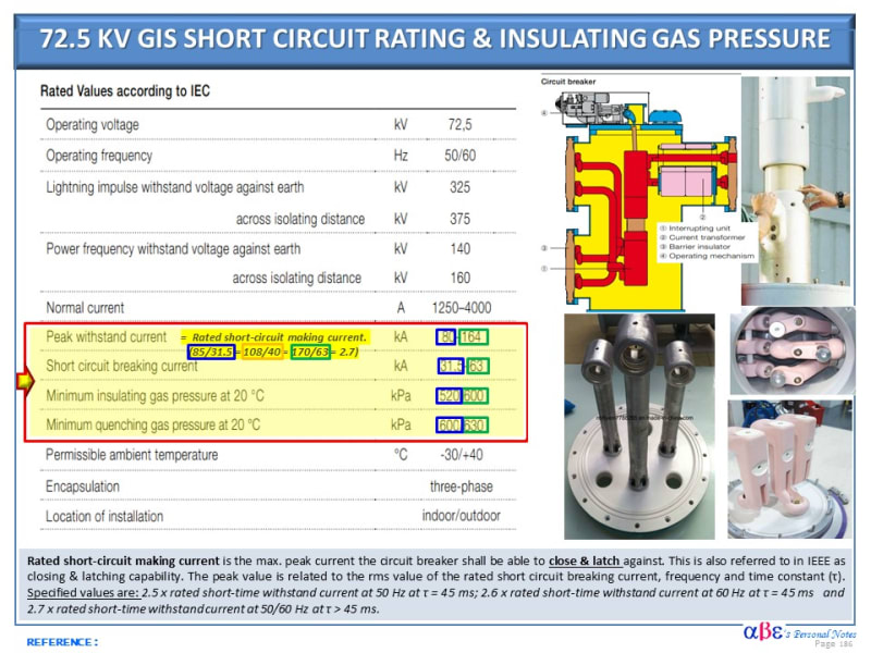
4) Can you explain this a bit more? These 13.8kv breakers appear to be 5-cycle breakers and are overdutied as well so may need replacement. How does a faster clearing time here impact fault duty on the 69kV bus if both interrupting and momentary are of concern? Significant SC contribution is attributed to the 13.8 kV, 83 MW generators. A faster circuit breaker and protective device with potential synchronous control help to reduce the thermal and dielectric stresses on the GIS. Two physical requirements (regimes) are involved: Thermal & Dielectric Regime. The forces on the GIS busses are usually not the limiting factor. However, only the GIS manufacturer can check if the busses, vessel, disks, and other components have an opportunity to be uprated for higher SC. The publication below provides generic data regarding the typical SC, close & latch, peak current rating and minimum insulated gas pressure recommended.
Thermal Regime: The hot arc channel has to be cooled down to a temperature low enough that it ceases to be electrically conducting.
Dielectric regime: After the arc extinction, the insulating medium between the contacts must withstand the rapidly-increasing recovery voltage. This recovery voltage has a transient component (transient recovery voltage, TRV) caused by the system when the current is interrupted. If either of these two requirements is not met, the current will continue to flow for another half cycle, until the next current zero is reached. It is quite normal for a circuit breaker to interrupt the short-circuit current at the second or even third current zero after contact separation


5) Are you referring to a faster scheme on the bus itself like a buss diff or similar? How does a faster scheme help reduce momentarily and/or interrupting duty on buses and breakers? Wouldn't overdutied momentary vault value still exist at the onset of fault regardless of relay timing? See above

6) We've explored these at some of the lower 15kV levels. These cannot be applied at 69kV to the best of my knowledge. I-limiter or CLiP Current Limiting Protector is limited to Medium voltage circuits.

GIS_SC_Rating_Gas_Pressure_mhl1al.jpg
 
cucky2000

Thanks for the information that is helpful. It looks like with faster clearing times the GIS could potentially withstand a larger fault current (momentary and interrupting)based on current construction or the potential for manufacturer to beef up components.

Does this similar approach with faster clearing time also apply to Air Insulated switchgear? I know bus bracing can be considered to provide higher momentary rating but have never heard faster clearing time as a consideration for increasing withstand rating?

Another question comes to mind with this new configuration resulting from the limitation to tie the new Substation to Existing Substation due to the potential to over duty existing substation. A 69kV tie connection with a reactor is being considered but I was wondering if it is practical to consider the flow of current as shown in the attachment with the generators from new substation flowing back up through 138kV system and back down from 138kV to 69kV bus on exiting substation? Is this practical? My initial thought is that it would present metering challenges and you'd have losses across the multiple transformers.
 
 https://files.engineering.com/getfile.aspx?folder=ddb52a30-036d-41f8-a32b-fec2dfbceb76&file=New_69kV_Configuration_Oneline_Markup.pdf
Yes, the same approach also applies to the AIS substation. The most common is to replace the post insulator with higher cantilever strength, increase the number of insulators or provide a shock absorber to mitigate the effect of the kI2peak.

Although it is possible to change for a faster relay scheme, obtain an exception in a utility environment may be a time-consuming proposition trying to convince the Standard Group, P&C Department, relay setting team, lab testing, O&M personnel, interface with neighbor utility and the local ISO.

.....if it is practical to consider the flow of current as shown in the attachment with the generators from new substation flowing back up through 138kV system and back down from 138kV to 69kV bus on exiting substation?]
If the problem is solved safe, reliable, and cost-effective this could be an option to consider.

It is noted that the 138 kV transformer has a Z=15% may help to damp the SC effect. Also, the Delta wye with impedance grounding may help limit ground faults. That provides some hope to get a reasonable system solution. Unfortunately is hard to guess what happens without modeling the system to determine the limitation.

QUESTION: Are anyone performing a holistic system study?

 
Status
Not open for further replies.

Part and Inventory Search

Sponsor