Continue to Site

Eng-Tips is the largest engineering community on the Internet

Intelligent Work Forums for Engineering Professionals

  • Congratulations IDS on being selected by the Eng-Tips community for having the most helpful posts in the forums last week. Way to Go!

92 volt touch potential 2

Status
Not open for further replies.

Mbrooke

Electrical
Nov 12, 2012
2,546
I'm really confused by this engineering article. How can the maximum touch voltage be 92 volts on a 230 volt system when in theory it ought to be 115 volts or higher?


In case of a system voltage of 230 Vac phase to neutral, the reason why a time of 0,4 seconds is specified is because 0,4 seconds is the maximum time a person can be subject to 92 Vac. That is the normative touching voltage in a TN system operating at 230 / 400 Vac.

Huh? [3eyes]
 
Replies continue below

Recommended for you

That is a company based in Italy.
I have no idea of the equipment bonding/grounding methods in IEC land.
I would not apply that information in North America.
Consider the case of a motor running at 230Volts to ground and grounded to North American Specs.
In the worst case, a winding fails to ground at one end and the whole 230 Volts is applied to the motor frame.
The phase conductor and the equipment grounding conductor will form a voltage divider.
All things being equal, 50% of the supplied voltage or 115 Volts to ground will be present on the surface of the motor.
All things are not equal.
In North America the equipment grounding conductor is typically two gauge sizes smaller than the phase conductors.
Considering the circuit as a simple resistive voltage divider substantially more than 115 Volts may appear on the surface of the motor.
Both the supply conductor and the equipment grounding conductor are typically contained in the same cable or raceway.
Any comments on the respective inductive reactances and the resulting impedances are welcome.

Bill
--------------------
"Why not the best?"
Jimmy Carter
 
NEC often results in more than two gauges in EGC size reduction- up to 10-12.5% of the phase conductors, so breaker clearing time would really matter.

The thing is you're right- assuming phase and EGC are the same size it is technically 50/50 relative to remote earth. But the 92 volt number has me confused.

Perhaps the circuit reactance has something to with it? Dunno.
 
EGC sizing in the NEC is based on providing adequate fault current to trip the phase overcurrent device before the ground wire overheats. Nothing to do with touch potential that I'm aware of.

Dave
 
In the CEC the size of the grounding conductor was based on the rating of the protective device for many years.
The rule was changed and the size of the equipment bonding or grounding conductor is now based on the ampacity of the phase conductors.
Hence, if the phase conductors are oversized to compensate for voltage drop, the grounding conductor must also be increased in size.

Bill
--------------------
"Why not the best?"
Jimmy Carter
 
92 Volts?
That could happen if the grounding conductor was a greater cross sectional area than the phase conductors.
I have no idea of grounding conductor sizes in IRC land.

Bill
--------------------
"Why not the best?"
Jimmy Carter
 
Mbrooke,

We should no be confused between the application of system voltages with determining the maximum tolerable safety voltage for equipment grounding (earthing) system.

The ANSI and IEC have different approaches to address the safety requirement and clearing time associate with protective devices.

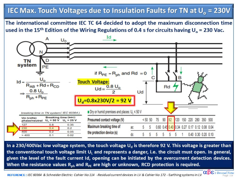
For a low voltage system 230/400 V, the max. touch voltage allows by IEC Standard associated with different grounding (earthing) system are as follow:
[ul]
[li][highlight #FCE94F]92 V[/highlight] for a TN (if RPE = Rph and Rd = 0 )[/li]
[li]115 V for TT (if Ra=Rb).[/li]
[/ul]​

See below for more details with the rationale for the published max. touch voltage of [highlight #FCE94F]≤ 92 V[/highlight]

Hope this help

>>>>>>
Touch_Voltage_Max_IEC_Std_LV_230V_dxo61m.jpg
 
In the CEC the size of the grounding conductor was based on the rating of the protective device for many years.
The rule was changed and the size of the equipment bonding or grounding conductor is now based on the ampacity of the phase conductors.
Hence, if the phase conductors are oversized to compensate for voltage drop, the grounding conductor must also be increased in size.

The NEC is the same, I believe.
 
I think the phrase was misspelled. In my opinion it must be said so:
according to IEC 60497 0.4 seconds is the time until which 230 V can be tolerated while 92 V can be tolerated for 2 seconds.
 
7anoter4,
A touch voltage of 230V can be tolerated safely for only ~0.13s max. per IEC 60497 for dry conditions
Similarly, 92 V can be tolerated for 0.4 seconds max.
For wet conditions, the clearing time of the protective device should be much less than the time mentioned above.
[highlight #FCE94F]A person will be electrocuted if subjected to 230V for 0.4 s (20 Cy @ 50 Hz).[/highlight]
 
230 Volts phase to phase is 132 Volts phase to ground.
92 Volts is 69.7% of 132 Volts.
If the equipment grounding conductor is 4 AWG sizes smaller than the phase conductor than this is close to the expected voltage to ground.
The Schneider Table posted above makes several unexplained assumptions, and uses several poorly defined terms.
The Schneider Table posted above shows general formulae without numerical values and then uses them to develop final values.
Takeaway from the table: The regulations have adopted a maximum disconnection time of 0.4 seconds for 230 Volt circuits.
After that is somewhat confused.

Bill
--------------------
"Why not the best?"
Jimmy Carter
 
Waross,

Notice that there is confusing information on the original post mentioning 230 V and 115V in the first sentence.
However, the quote and link clearly refer to a max. touch voltage 92 V per IEC Std for a system voltage of 230/400 Vac.
[ul]
[li]The voltage phase-to-phase =400Volts[/li]
[li]Nominal phase-to-ground 400/1.73 ~ 230V.[/li]
[/ul]​
 
Cuky, our original poster was unfamiliar with European 230/400 Volt three phase systems and took it to be a center tapped 115/230 Volt system.
I didn't realize that until I saw your post.
Then it became clear that the 92 Volts was on a 230 Volt to ground system.

Bill
--------------------
"Why not the best?"
Jimmy Carter
 
I have worked under engineering standards that would call for a motor frame to be grounded with #2 AWG copper although a #14 AWG or #12 AWG copper conductor would satisfy the code.
The calculated touch voltage was nil.

Bill
--------------------
"Why not the best?"
Jimmy Carter
 
Waross,

I understand what you say recognizing that many of us in this forum are more familiar with the regional standards applicable in NA. Due to globalization, we as engineers are exposed more than ever to multiple international standards and particularly the European codes including IEC, CENELEC, BS, Chinese, Japanese, and other engineering standard practices that many times fascinating to see the diversity of approaches to solving electric problems but very challenger to keep us updated.

The good news is this exercise keeps our neurons alive during our final career or enjoying an honorable retirement.
 
Hi 7anoter4,

Thanks for sharing with us the excerpt from the British Standard BS EN 50522, Earthing of power installations exceeding 1kV a.c. Please help us out to verify if this standard is applicable to LV 230/400V TN system and if compatible with the IEC Std 60364-4-41: PROTECTION AGAINST ELECTRIC SHOCK.

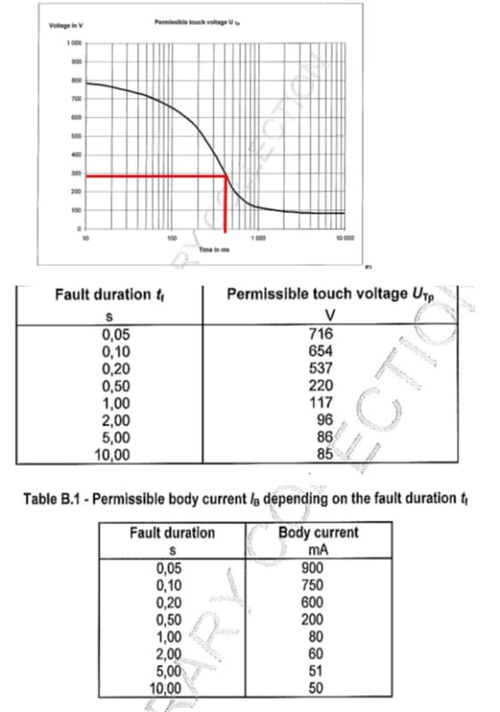
The link provided in the original post by Mbrooke contains a graph (see below) derived from the IEC Std 60364-4-41 indicating that 92Volts is the maximum tolerable touch voltage for a TN system 230/400V in dry conditions.

Fill free to estimate from the curve below the max. clearing time for 230V and verify if is satisfactory close to ~0.13 sec.

Asset%203@4x-100.jpg
 
First as far as I know no permissible touch voltage against time curve it is shown in IEC 60497-1 but only IB[body current] in 4 situations[AC1,AC2,AC3,AC4[4.1,4.2,4.3].Figure 20.
I think AC4.1 has to be the limit for EN 50522.
However, it is referred to 1 kV and more. So for 0.4 sec permissible current is 230 mA.
The body impedance 1000 ohm then the permissible voltage for 0.4 sec is 230 V

 
Ok- but why does the voltage dip to 92 volts and not 115 volts?
 
I have not a IEC 60346-4-41 copy with me but I have a copy of Schneider Electric - Electrical installation guide 2008
and the explanation in chapter 6.2 Protection against indirect contact [for TN system] it seems to me logical.
First the body current curve AC4.1 [the left side limit of AC4.1 area ] used, so it is lower than what EN-50522 took [the right side limit-so higher].
Second, if the phase conductor impedance equals PE conductor impedance the voltage between fault location and ground will be 230/2=115 V. If the voltage drop will be 20% then
this voltage will be 92 V.
From chpt.3 Protection against indirect contact. Specified maximum disconnection time:
“The IEC 60364-4-41 specifies the maximum operating time of protective devices used in TN system for the protection against indirect contact:
- For all final circuits with a rated current not exceeding 32 A, the maximum
disconnecting time will not exceed the values indicated in Figure F13.
- For all other circuits, the maximum disconnecting time is fixed to 5s. This limit enables discrimination between protective devices installed on distribution circuits”
Fig.13 for 120<Uo<230 t=0.4 sec.
In my opinion, nevertheless the minimum voltage to ground it could be 0.8*115=92 V if the PE connection is damaged and interrupted it could be total Uo=230 V so the disconnecting time remains 0.4 sec.
 
Status
Not open for further replies.

Part and Inventory Search

Sponsor