Eng-Tips is the largest engineering community on the Internet

Intelligent Work Forums for Engineering Professionals

A couple of modal analysis puzzles 1

Status
Not open for further replies.

GregLocock

Automotive
Apr 10, 2001
23,120
0
36
Orbiting a small yellow star
(1) As we know a linear system can't have two modes with the same resonant frequency, otherwise the universe explodes or something like that. So consider a cantilever beam with a rectangular cross section. It clearly has an (approximately) quarter wave mode in each direction. Now reduce the large dimension towards that of the smaller. The frequency will drop. Now make it equal. We can't have two modes at the same frequency, so what happens?

(2)If we add constraints to a system the frequency increases. Take a slender rod in free space, its first mode has nodes perhaps 1/5 of the way in from the end.
image_2024-04-25_160301516_kmdn7a.png

Now restrain the ends with pin joints. The nodes are obviously at the ends of the rod, and the frequency has dropped, not increased.
image_2024-04-25_160433813_yzjgyk.png


I know the answer to (2), I think. (1) may be based on a false assumption.


Cheers

Greg Locock


New here? Try reading these, they might help FAQ731-376
 
Replies continue below

Recommended for you

Free-Free B.C. for slender beam:
fi=Lambda^2(EI/m)^0.5/(2 pi L^2)

Lambda(1)=4.7304074, etc.

Courtesy "Formulas for Natural Frequency and Mode Shapes." No meaningful assumptions, other than gently taping the beam while in free-fall.

 
I like a good quiz. Thanks for keeping the forum interesting!

I'm confused by the first question.

(1)...So consider a cantilever beam with a rectangular cross section. It clearly has an (approximately) quarter wave mode in each direction. Now reduce the large dimension towards that of the smaller.

I tend to think we can analyse the two principle axes of the beam independently (in absence of some cross coupling mechanism such as gyroscopic action or sliding bearings in rotating machines). For simple square cross section fixed/free beam I'd expect the same natural frequency in both directions (symmetry demands that it be so). I'm sure there's something subtle in your question or a piece of the paradox or contradiction that is not jumping out at me.

(2)If we add constraints to a system the frequency increases. Take a slender rod in free space, its first mode has nodes perhaps 1/5 of the way in from the end.

Now restrain the ends with pin joints. The nodes are obviously at the ends of the rod, and the frequency has dropped, not increased.

Yes it's a challenging question. How can natural frequency increase when we add constraints (in going from free free to pinned pinned)?

...The answer (as you know) is that it didn't. The first natural frequency of the free free is zero hz (corresponding to translation at a constant velocity) which is lower than the first natural frequency of the pinned / pinned, as expected. It is the second natural frequency of the free free which is higher than the first natural frequency of the pinned pinned.

Actually.... I think you shared this 2nd one way back a decade or more ago, and the answer rattled around out in my brain all these years and happened to fall out at the right time. I probably wouldn't have figured it out otherwise. On the bright side, it also suggests you've had a lasting impact on me... I remembered a little tiny fraction of all that stuff you shared!

 
Yes I like the second one, it is subtle. I /think/ the first one relies too heavily on this "As we know a linear system can't have two modes with the same resonant frequency"... but all my experience says that that is true. If you have two systems with the same frequency and tie them together, you get two modeshapes with different frequencies.

But this tying together is bad wording. Two spring mass systems in parallel, for example will resonate at their original frequency. Sure in series you get the classic split frequencies used in dynamic absorbers.

In real mechanical systems it is very hard to arrange for a case where the two systems remain isolated from each other and there is no cross talk between them yet share common excitation.

Cheers

Greg Locock


New here? Try reading these, they might help FAQ731-376
 
(1)[ ] I agree with Greg's second post, where he queries his earlier "as we know a linear system can't have two modes with the same resonant frequency" assertion.

(2a)[ ] Let's go a bit Zen for a moment and broaden our concept of a constraint.[ ] The first beam can then be viewed as having a pair of constraints, but we cannot see them.[ ] We can only detect them indirectly through their effects, which are to prevent the points to which they are attached from moving laterally.[ ] The fact that they do this without having to exert any force is a mere coincidence.[ ] Under this view we have not added any extra supports in going from the first beam to the second, so we have no reason apply the "if we add constraints to a system the frequency increases" dictum.

(2b) If Zen is not your thing, start with the first beam then envisage gradually moving the pair of supports symmetrically inwards.[ ] When you get to the configuration of the second beam the supports experience no dynamic force but they are still there, busily doing absolutely nothing.

[sub][ ]—————————————————————————————————[/sub]
[sup]Engineering mathematician / analyst.[ ] See my profile for more details.
[/sup]

 
Denial said:
so we have no reason apply the "if we add constraints to a system the frequency increases" dictum.

I know you know a lot more about this stuff than me, but I'm not sure I get your point.

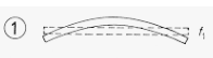
I agree there are lots of ways to "explain" why the free free modeshape shown is higher without considering constraints (I originally had in mind an explanation that the bending for a given peak displacement is higher for the free free modeshape so it's not hard to visualize that the ratio of potential energy to kinetic energy will be higher on the free free beam modeshape than the simply supported modeshape). But the more relevant question in my mind is what happens when we do consider adding constraints and why doesn't it match what we expect.

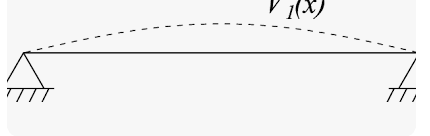
You have a comment focused on the role of the term "constraint", but I think we can reframe Greg's post without mentioning constraints in a way that demands further explanation (which is only satisfied by that zero frequency mode... at least from my limited viewpoint). So instead of talking about constraints, let's insert a pair of variable-stiffness discrete vertical spring elements into the pinned joints (between the support and the beam). Now lets' vary those discrete element stiffnesses from infinite stiffness (simply supported) down to zero stiffness (free free).... and the "natural frequency" goes up. It doesn't match what we know about mass spring systems (we don't expect the natural frequency to go up when we decrease a pair of spring stiffness within the system). It only matches our expectation if we note that we are comparing apples to oranges in terms of which natural frequency we are looking at.

In further analysis of that variable stiffness discrete spring experiment, let's say you plotted a curve of the resonant frequency as you decreased the stiffness of the inserted springs gradually from infinity down towards zero. You would see a continuously decreasing resonant frequency all the way until you got arbitrarily close to zero stiffness (at which point natural frequency is very close to 0). But when you get to exactly zero stiffness you have a choice: You can select the zero frequency...which is the logical continuation of tracking that first mode (it doesn't create any step change in natural frequency curve in between "close to zero" stiffness and "exactly zero" stiffness); or you could select the free free non-zero mode frequency which would introduce a step increase in your natural frequency curve between "close to zero" stiffness and "exactly zero" stiffness. It seems a very logical explanation for that step change would be that you are now looking at the 2nd frequency (you are comparing apples to oranges on the two sides of that step change in frequency).

I'm not saying you are wrong, because often what "makes sense" to explain something is very subjective. But fwiw Greg's explanation makes a lot more sense to me to explain the pieces that initially seemed perplexing.


GregLocock said:
In real mechanical systems it is very hard to arrange for a case where the two systems remain isolated from each other and there is no cross talk between them yet share common excitation

That's why your paradox didn't faze me. I've never played with anything like that in the real world. I based my mental model on simple textbook approximations.

If I try to visualize what you're talking about myself, let's say we have a square cantilever beam. Can the tip orbit in a circle in free motion? My intuition says it might do that at small displacements but not at large displacements. Maybe, I dunno.
 
I would like to revisit question 1.

As Greg said "In real mechanical systems it is very hard to arrange for a case where the two systems remain isolated from each other and there is no cross talk between them yet share common excitation"

So the question boils down a matter of whether the x and y direction motions are coupled or decoupled. If they are decoupled, then they act the simple way we predict from textbooks. If they are coupled, then things get more complicated.

Let's say we have a cantilever beam with axis in the z direction and with x and y radial directions having the same properties. Is motion uncoupled in these 2 directions?

I would argue that there is a coupling mechanism present if the beam has a square cross section which is not present if the beam has a round cross section.

If it is a round cross section then the bending moment of direction is the same no matter which way you bend the beam. If you push the tip off-center distance x0 in the x direction and y0 in the y direction, then the restoriong force in the x direction depends only on x0, not on y0.

But if it is a square cross section then the bending stiffness varies depending on which direction the beam bends. If you push the tip off center by a distance x0 and y0 then the restoring force in the x direction will now depend on both x0 and y0. It is no longer decoupled. At least that's my thought (would you guys agree?). I guess I would need to go through more algebra to prove it but that's what I think.

Once we have a cross coupling mechanism, then having natural frequency the same in both directions makes the cross coupling more notable (because resonant forces and and motions coupled from a first axis to the 2nd axis excite the resonance of the 2nd axis).

I don't think I discovered anything new but I'm still trying to catch up to you guys.

I vaguely remember hearing that a dynamic absorber should avoid having the same stiffness in the 2 directions. But I also recall seeing someone that fabricated a dynamic absorber by threading an all-thread rod into a horizontal motor top pad-eye socket. I wonder if such dynamic absorber would work with the round cross section but would fail if you tried to replace it with a square cross section.

 
I hate to say it but the only way I can think of resolving that is FEA. In a somewhat similar case with cars the first bending and first torsion mode have roughly the same frequency. In the bad old days you didn't get a bending mode and a torsion mode, you got a front end bending with rear torsion, and vice versa.

Mr belvins is silent on the matter, i suspect the answer is that in a symmetrical beam you only get 1 quarter wave modeshape.

Cheers

Greg Locock


New here? Try reading these, they might help FAQ731-376
 
electricpete said:
But if it is a square cross section then the bending stiffness varies depending on which direction the beam bends.
.

Whoops, my intuition was wrong on that one. Case 9 here
RotateRectBeam_n74nt5.gif


If it is square, then b=d and the moment of inertia dependence on angle has the form cos^2 + sin^2... which does not vary with angle.
 
Nice catch. Ah, I remember a similar issue. I was looking a the mode shapes of a brake rotor, I couldn't get a good mode shape using a normal accelerometer, as the mass of the accelerometer forced the repsonse to be nodal wherever it was mounted. The wavy mode shape just rotated around to accomodate that. Switched to hammer excitation, and of course the impact point was always antinodal. So I used sand s instead. Fun project. So, in a heavily symmetrical system the orientation of the mode shape is fixed by non linearities or small asymmetries in the structure.

Cheers

Greg Locock


New here? Try reading these, they might help FAQ731-376
 
Status
Not open for further replies.
Back
Top