Continue to Site

Eng-Tips is the largest engineering community on the Internet

Intelligent Work Forums for Engineering Professionals

  • Congratulations KootK on being selected by the Eng-Tips community for having the most helpful posts in the forums last week. Way to Go!

A Frame Cabin

Status
Not open for further replies.

LQQD

Structural
Apr 14, 2012
38
Hello everyone,

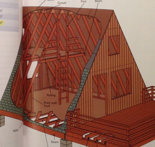
I'm assessing a friend of mine who is an architect who is working on a project of an A-Frame cabin as in the attached picture, he is using some drawings and references form some do it yourself books and asked me to check the designs. I don´t have much experience on wood design buy do have decent experience on steel and concrete design.

I'm concerned about the lateral resisting system to wind loading. Can´t see any brace on the plane of the rafters. Is the external plywood supposed to provide lateral restraint working as sheer wall? I've seen other drawings in which no braces are provided. Any source of information regarding this is welcomed!

Another doubt is concerning the unbraced length of the rafters, being attached continuously to sheeting provides sufficient restraint as to consider it continuously braced, no LTB?

Thanks!!
cabin_dvcnc0.jpg
 
Replies continue below

Recommended for you

To your 1st question: based on your rendering, continuous plywood sheathing to the roof should take your wind or seismic loads down to the level of the beam that sits between what appear to be masonry columns? (then the rendering cuts off) Essentially, you'll just need to check the complete load path: nailing of plywood on A-frame rafters sufficient to resist load, transferring load to beam via some positive connection, beam to resist load, transfer of load to masonry columns via some positive connection, masonry columns to resist load, and transferring of that load to concrete footings (looking at both shear and overturning the whole way down). Note that you will have to do this process in the other orthogonal direction as well (parallel to rafters). You might run into difficulty in this direction getting all the load to transfer downward due to all those openings in the wall.

To your 2nd question: yes, the continuous nailing to the compression face does allow you to consider LTB as zero.
 
Thanks Nor Cal SE! Regarding the 1st question, it think i wasn't clear enough, i was actually concerned about wind perpendicular to the plane of the A's. In this case i am trying to determine if the plywood sheeting could take the load or if i braces on the inclined plane of the rafters are necessary.
 
In that direction, the sheathing will act as a diaphragm taking the lateral load to the base, stiffened by the A-frame rafters... interesting what happens to the top of the piers, though.

Dik
 
Under wind pressure, is it possible for rafters on the leeward side to have compression on the inside face? If so, are you relying on drywall to prevent LTB?

BA
 

BAretired, yes, inside face of rafters do get compressed by flexure but bending moments on this direction are lower allowing for larger unbraced lengths.

Anyone has recommendations on how to nail down and connect plywood sheeting to each other and to rafters to assure right performance as diaphragm?

Thanks!
 
Where the loft does not occur, I would think there would be horizontal blocking between the rafters at about the 8 foot level to also help prevent LTB. Similar to fire blocking...

Mike McCann, PE, SE (WA)


Typically in residential construction you will use an unblocked diaphragm with 5/8" sheathing nailed to the rafters at 6" at panel edges, 12" at intermediate supports. So you wont attach the sheathing panels to each other, you will adjoin the panel edges to align with the rafters and nail to them. You also will want to stagger the panels so the edges don't align with each other. I believe this gives you a shear capacity of around 230 plf, you can double check on the link BA posted. I don't think you will have higher shear values than this.

As far as the lateral forces on the endwalls. You could model the endwalls as trusses with diagonal braces and try to resist the lateral forces that way, although Im not sure how well it will work. If you want to use the plywood sheathing you could try to use the triangular segments at the end as shearwalls, you would just need to have hold downs from the studs to the bottom chord of the truss at the edge of the door and window openings. Either way the endwall needs to be able resist out of plane wind loads as well. You will need to have a built up column in between the door and the window that goes from the floor to the roof diaphram that will support a majority of the wind load.
 
BAretired, thank you so much!! that is exactly what I was needing! really helpful!!

dnlv, thanks for the tips I haven't finished reading APA's document yet, maybe i'll come back later on your suggestions! I was supposing all lateral forces (parallel to the plane of the A frames) go through the horizontal component of axial force on the rafters, as will be for A's on the middle of the walls, far away from end walls. In my structural scheme no lateral forces will be resisted by the endwalls. I'm not sure if you where referring to this situation though, maybe I'm missing something!

Thanks!
 
LQQD,

You're right, my dumb brain is stuck on conventional residential framing. If you can use each truss as a lateral resisting element, that is the way to go. You will need to tie the trusses down to the beam to resist overturning, if the forces or light enough you can probably just use typical hurricane ties or truss screws, also size the beam for those loads and tie the beam down to the pilasters for adequate uplift resistance. In the direction parallel to the end walls you will not have any diaphragm shear, since each frame is taking equal force. In the other direction you will have diaphragm shear, you will probably be fine with just typical 6/12 nailing pattern with no blocking, assuming you are not in a high wind area. You should however block at the panel edges of at the ridge and at the base so you have proper diaphragm boundary elements.

As far as the end walls, you will need to size the studs to transfer wind loads into the diaphragm, you should also block between the trusses in the first few exterior bays to help carry the horizontal reaction from the studs into the diapragm. I attached a few details that will hopefully help.
 
 http://files.engineering.com/getfile.aspx?folder=92434ba3-b21a-4098-bcc6-407e44a925fc&file=Details.png
dnlv,

I'm sorry I'm replying so late, thank you very much for your word, really helpful. Also thanks for taking the time to do the sketches! All will be reflected on the final design!

Thanks again!

PLQQD.
 
Status
Not open for further replies.

Part and Inventory Search

Sponsor