Continue to Site

Eng-Tips is the largest engineering community on the Internet

Intelligent Work Forums for Engineering Professionals

  • Congratulations KootK on being selected by the Eng-Tips community for having the most helpful posts in the forums last week. Way to Go!

A query on EN 13121-3 about conocal ends (European code for FRP tanks and vessels) 1

Status
Not open for further replies.

johntokarev

Structural
Jul 23, 2006
4
Hi

In chapter 10.4.4.2.2 has 2 variant:
a) for short conical shells - L < 6*Dm
and
b) for long conical shell - L > 6*Dm

And has Figure 7, but i dont see L and Dm:
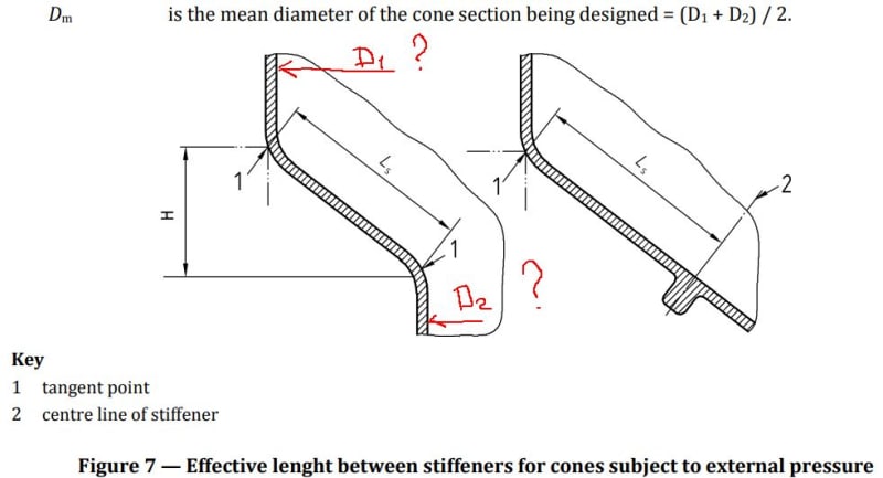
Fig7_wn0zn6.jpg


Ok, i think D1 and D2 a draw red pen, so Dm = (D1+D2)/2
What is L? L=Ls? Where i can find L value? L is all length/height of tank?
 
Replies continue below

Recommended for you

John

Welcome to the wonderful world of bad specification writing, bad translating, bad editing, bad proof
reading, and diagrams that don't make sense.

I trust you know this is about fifth attempt to produce a working standard by CEN.

Looks like you have 2016 version.

Ls distance between two stiffeners or supports (inc stiffened regions). Dm mean diameter of cone.

I think L is Ls (as small distance between stiffeners (any) will have an effect.

Best solution/check is to design cone to BS4994 to check logic of decisions regarding dimensions to use.

Have you seen note after (Eq 62)?


Regards

Ed

Ed Clymer
Resinfab & Associates
England
 
Thank you very much for your reaction to my question.

Ok, I'll try to accept your offer that L = Ls.
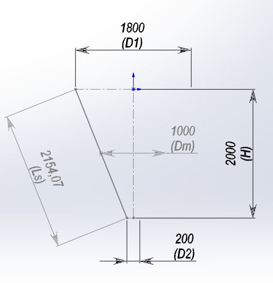
Then in the picture below the "short" cone:
L = Ls = 2154 <6 * Dm = 6 * 1000 = 6000
short_akmwqw.jpg

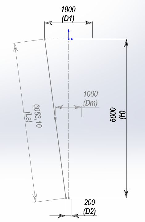
And in this picture "long":
L = Ls = 6053> 6 * Dm = 6 * 1000 = 6000
long_doiv8k.jpg

The vast majority of my cones will be "short".
This seems to be true, thanks.

The note after formula (62) I saw, it concerns the design of stiffeners and the selection of their section. While the question is about the critical force of the wall of the cone, I try not to use the stiffeners on the cone.

The calculation of the cone with BS 4994 cannot be compared, since the procedure for calculating the conical heads for external pressure there is the same as for cylindrical walls with a change in Diameter to "D / cos a" (see 18.4.4)

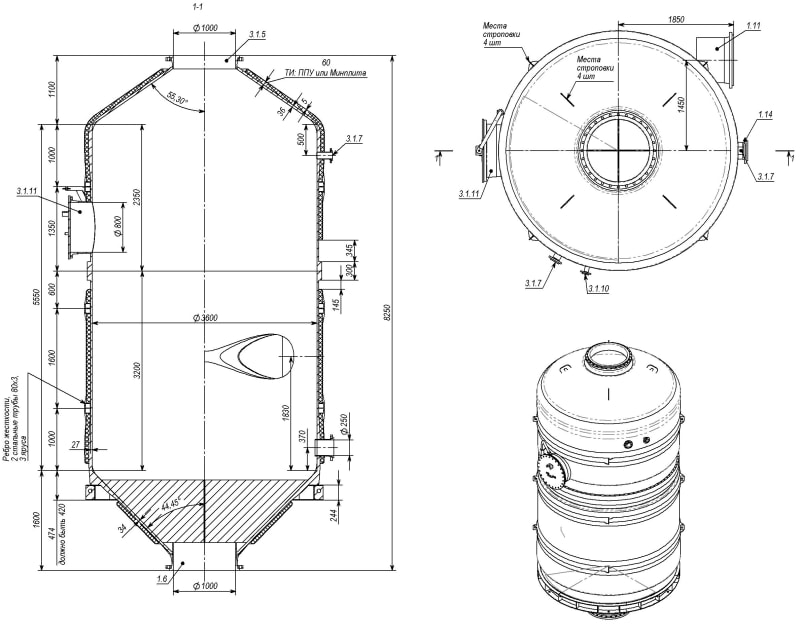
Howling I am trying to calculate a fiberglass vacuum evaporator to 100% vacuum, and this is what comes out so far:
View_vcyhf2.jpg

Sorry for my English, I am using an online translator.
 
John

I think your diagrams are correct: L[sub]s[/sub] is slant length and you can find mean diameter.

Whilst BS4994 and EN 13121-3 are similar, the original set up of material properties are widely different
ie 4994 has a calculated K value (to derate laminate ultimate strength) and a minimum K value of 8.
But it is a well tried and tested procedure; so it is wise (if in doubt) to check using that code) with correct
input (material) values.

Part 3 is of course for vessels (rather than tanks) and includes Eurocode. The logic is; 'we have it so might as well
use it'. The source of equations in part 3 is unknown.

It will be interesting to see what final values of laminate you calculate. As yet,. no one knows if there is any benefit
in using part 3. Perhaps for a vessel the answer is yes - but there is some very expensive testing yet.

What data did you use for material properties and was testing to parts 1 and 2 (as suppliers in UK refuse to test to parts
1 and 2 claiming 'no demand'. What characteristic material values are you using?

Did you know there was a part 5 to EN 13121? Which is an example of a closed vessel.

I spent three whole months on a simple vertical, cylindrical, tank to part 3:2016... and then found CEN had issued eleven pages
of corrections... there is also a 2020 version.


Regards

Ed


Ed Clymer
Resinfab & Associates
England
 
Hi, Ed
In BS 4994 Kmin is 8 (9.2.2). In EN13121 Kmin is 6 or 8 for basic design (table 8).
Material properties is equal to: BS4994 table 5, EN13121 table 3.
But EN 13121 more flex and complex, see properties for WR in table 3.

Conical bottom calculated according to BS is thicker than in EN.

Yes, i see part 5 EN13121б but i dont understand many things.

Do y have "pages of corrections" or 2020 version?
Can you send me?
 
John

The 'K' in 4994 is not the same as the 'K' in part 3. The whole methodology is different
but it is good to compare the two systems - just in case another (as yet unnoticed) error has
been found. I helped write 4994 (87) and are therefore biased. The EU wanted a new/different code
that worked with the PED (and could use Eurocode). Part 3 is simply not a good standard for tanks.

I have hundreds of conical bottoms all working without problem; in fact never had a problem with
a 4994 item correctly designed, built, installed, and certified.

Part 5 was supposed to be an exemplar on how to design a tank (but they used a pressure vessel instead -
a very expensive pressure vessel). Written in German - like part 3 (then badly translated) with an
intention to mislead, or at least not to be helpful.

I do not have the 2020 version (in UK no demand for such items - despite me spending 3 month on an example).
And I have not recovered from the £700 cost of the first version - which was simply rubbish.

Have you calculated the manhole flanges yet? What gasket stress have you used? What gasket material?

I do have the eleven pages of corrections in PDF; but have no way of sending and (I think) this page will
not let me use an email address. Try a web search for Resinfab & Associates and call.

You are no alone in not understand part 3 or 5: I don't think anyone actually understands them.

PS: I will try and find the eleven sheets and then need a way of sending to you.

PPS: If you are using MathCAD do not redefine 'N' (newton) as something other than 'N' for newton.

Regards

Ed


Ed Clymer
Resinfab & Associates
England
 
John

I have found the eleven pages. My understanding is this was a list of complaints,
errors, changes and mistooks on 2016 version of part 3.

It is a PDF document and I will attach.

(I have attached, what happens next is unknown - but I do hope it works.


Regards

Ed

Ed Clymer
Resinfab & Associates
England
 
 https://files.engineering.com/getfile.aspx?folder=fb44cacb-a5be-4324-9d59-238dea3695f6&file=Changes_to_part_3_for_2020.pdf
John

I have just checked and am quite astonished that the PDF was transmitted and available for all to see.
(I have rather low expectations of technology)

Hope you enjoy all the editing and deleting you will now have to do (I am glad to see back of (square root (A[sub]5[/sub]) ) etc.


Regards

Ed

Ed Clymer
Resinfab & Associates
England
 
Many thx for changes 2016 -> 2020

>>Have you calculated the manhole flanges yet? What gasket stress have you used? What gasket material?
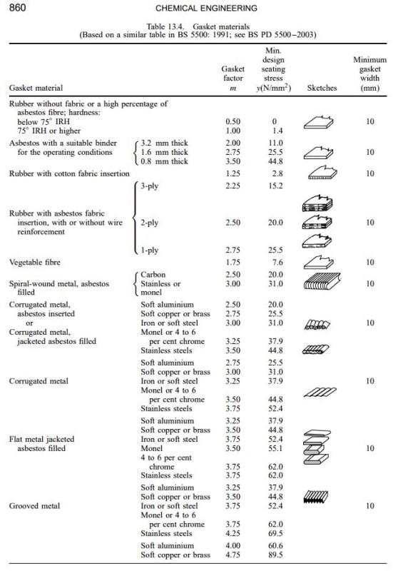
We calculated the flanges of the hatchways. I took the data on the gaskets from the book "Coulson & Richardson's Chemical Engineering", page 860, attached
page_860_gaskets_rmdct1.jpg

I use Rubber whithout fabric below 75IRH

All book at link
 
John

Your reply regarding stress to gasket is zero, simply can not be true. There has to be a value otherwise leakage.

BS4994 suggests (and has always worked for me) at 2.32 MPa (N/mm[sup]2[/sup]) For many years we have used EPDM gaskets because they tend to be softer than the thermoplastic face of
the flange (in UK we build a lot of thermoplastic lined (PP or PVC-U) /GRP) external tanks (and some vessels). The soft EPDM seems to cope with surface scratches better.

The objective is to compress the gasket (over a narrow band just inside the bolt circle) say a width of 5 mm - 6 mm.

Flange design to BS 4994 were copied from BS 5500 (steel construction) - which has a minimum seating stress of 2 MPa (for soft rubber).

EN 13121-3 uses two (2) different gasket stresses Qmin (seating stress) of 2.5 MPa (without reference to actual gasket material). And QsminL.

Part 5 uses 5 MPa operating (QSminL( and 6 MPa bolting up stress (Qmin). But part 5 is very thick all GRP flanges and was not intended to be helpful.

In the eleven pages of corrections; I think one of the things corrected was gasket stresses.

In the UK we are plagued with rubbish grade EPDM sheet. From China (of course) with lots of cheap fillers - making the EPDM far less soft than it should be.
(but it is cheap).


My plan. We had three grades of EPDM (50 - 65 IRHD) tested for compression modulus by Semperit of Austria (a trusted manufacturer). From that data I can determine
what stress is required to compress the gasket by 33% and 50% (via FEA models).

There is a document by The European Sealing Association (title Tightness in gasketed flanged unions) and refers to EN-1591-1 standard. It also lists no less than
five gasket parameters (surface stresses) which are used to calculate the flange/gasket/bolting.

I reckon the gasket stress should be between 2 and 4.5 MPa (unless good reason not to be).


How are you progressing with your gasketed flanges?

Regards

Ed


Ed Clymer
Resinfab & Associates
England
 
Status
Not open for further replies.

Part and Inventory Search

Sponsor