Series_70
Mechanical
- Mar 29, 2017
- 1
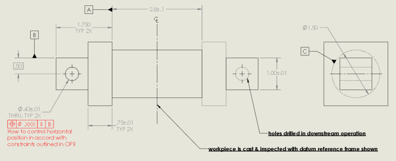
Note — some dimensions and GD&T callouts that are likely irrelevant to discussion aren't depicted in my mocked-up illustration. I'm fairly new to GD&T— I've learned what I know online (often trolling here — thanks for all the help!) and from our senior engineers when they have a spare minute. On to my quandry (please refer to attached mockup illustration):
[ul]
[li]'A' is a datum feature of size — for better & for worse, this is a hard constraint. I promise that we had reasons for this![[morning]](/data/assets/smilies/morning.gif "[morning] [morning]") .[/li]
.[/li]
[li]The 2x through holes have to be machined in a downstream operation controlled with its own dedicated machining drawing.[/li]
[li]I only care about controlling the true position of the holes with respect to the square bosses' boundaries (please refer to image),
[li]<I think> I can rule out using one of the 'flange' faces as a primary datum feature in the machining drawing, as our casting datum feature 'A' is a feature of size – controlling left and right holes' positions via TP to a flange face
[/ul]
Bottom line: how could I control location of the 2 through-holes in the downstream machining op drawing so they're identically controlled with
respect to the material boundaries of the bosses through which they're respectively drilled?
This one has been a real head-scratcher for me. I'd appreciate any feedback you folks can give me.
[ul]
[li]'A' is a datum feature of size — for better & for worse, this is a hard constraint. I promise that we had reasons for this
.[/li][li]The 2x through holes have to be machined in a downstream operation controlled with its own dedicated machining drawing.[/li]
[li]I only care about controlling the true position of the holes with respect to the square bosses' boundaries (please refer to image),
i.e., holes can't encroach too close to either 'left/right' boundaries of the boss through which they're drilled.
[/li][li]<I think> I can rule out using one of the 'flange' faces as a primary datum feature in the machining drawing, as our casting datum feature 'A' is a feature of size – controlling left and right holes' positions via TP to a flange face
would not satisfy the previous requirement, as the holes have the original feature of size between them.
[/li][/ul]
Bottom line: how could I control location of the 2 through-holes in the downstream machining op drawing so they're identically controlled with
respect to the material boundaries of the bosses through which they're respectively drilled?
This one has been a real head-scratcher for me. I'd appreciate any feedback you folks can give me.