Continue to Site

Eng-Tips is the largest engineering community on the Internet

Intelligent Work Forums for Engineering Professionals

  • Congratulations cowski on being selected by the Eng-Tips community for having the most helpful posts in the forums last week. Way to Go!

A rudimentary BC Question

Status
Not open for further replies.

Burner2k

Aerospace
Jun 13, 2015
193
Wanted to get some additional information on how to model the following in FEM.

If I want to simulate a plate with biaxial loading with or without shear acting along the edges, what are the different possible boundary conditions which can be specified to capture the deformation pattern accurately (sides of the plate having no curvatures when deformed)?

01_nqtbyh.png


02_cqrpaj.png


Thanks...
 
Replies continue below

Recommended for you

In my experience, whey you constrain the corners, some people do it properly and some do not (quite often incorrectly). If you do it correctly, there will probably be localized stresses at these constraints; you then have explain to approvers why these occur and why it is acceptable (this can go smoothly or may not). It is a good and acceptable approach, but sometimes I avoid this approach just to avoid the potential hassle down the road. 20 years ago I took a FEA class at the company I worked for and a similar problem came up. He said you have to use symmetry. While it worked for the given problem, I asked what to do if symmetry does not exist; he had not answer. I thought there must be some reasonable options. One advantage of the soft springs approach is that you don't get the localized stresses so it usually gets approved with ease (in my experience).

It is a good problem to think about and discuss. I think setting up proper boundary conditions is one of the biggest challenges and a common source of error.
 
IMHO you never Have to use symmetry to solve a FE problem. Symmetry reduces the size of the problem, but with computer speed and space these days, is it really worth it ? given the possibility of effing up the symmetry constraints, given the near certainty of unsymmetric loads, ...

another day in paradise, or is paradise one day closer ?
 
In this case internal loads are already balanced, Inertia Relief have to balance only near zero loads? produced from roundoff errors.
Structure with unbalanced loads must be constrained.
I Run two analisys First with weak spring and second with Inertia Relief (option INREL = -2, solver celect node to ballance model automaticaly).
Nodal displacements look like different because two models expand relatively to different nodes. But Displacements can be recalculated or I can use option INREL -1 and manualy select node.
Stress and strains are the same.
In FE problems I always use plane and axial symmetry if it is possible - symmetrical loads and constraints.
Axicymmetry can reduce modes size dramaticaly. 50-100 times. Without Reduction of accuracy and without some artifictial errors, like non smooth stresses in snap-fit problem due to contact of two meshes.
In TS problem without shear loads we can reduce model to 1/8.
Off course newer use Symmetry in Modal analisys and Dynamic problems.
1_upuaih.jpg

2_tnd77o.jpg

3_vskan0.jpg

4_fqoa0b.jpg

5_xhw76v.jpg
 
yes, those links describe the approach suggested above, using a minimum number of constraints to remove RBM.

another day in paradise, or is paradise one day closer ?
 
Folks,
Thanks for the replies & continuing the discussion.

ESPComposites, thanks for giving additional pointers. Was really busy last week. Hopefully, next week I will get a chance to redo the problem with your suggestion.

Karachun, nice of you to post pictures of your FE model setup. Setting up accurate BCs to capture the deformation pattern accurately is probably one of the more challenging aspects of FE modeling.
 
ESPComposites,
I tried running the FE Setup based on your suggestions...still getting RBM.

Problem Setup Shown below: The plate (surface) is constrained in TZ, RZ, RX & RY (in earlier iterations, I started off with constraining just TZ and progressively added additional constraints)

aaa_acmz9j.png


Node 294 where RBM is occurring (end of orange on the plate in the picture). The affected node is same.

bbb_z8rqmh.png


DOFs affected by RBM or excessive change in stiffness.
ccc_i1tsuz.png


Ran with BAILOUT option and it is hard to make out the nature of RBM.

eee_j1rieq.png


Just showing 1D springs allowing DOF. Springs to which red lines are connected are those where TX motion DOF is allowed & Oranges indicate vertical (TY) DOF is allowed. I hope I am correct in interpreting how 1D springs work i.e. activated DOF is the direction along with springs allow motion to occur.

ffff_venxcu.png


Lastly, spring property definition. I also tried lower values.

ggg_msuhwd.png


If you have any suggestions on how to make the above work, please let me know. As you have written in one of your posts, this method works but I just can't seem to figure it out how.
 
Burner2k can you post .modfem or .dat file here. Try to use Spring Damper elements instead of Dof-Spring, the second type must have aligned nodes in stiffness direction.
Also constrain one node in TZ dof is sufficient to prevent translation in Z direction.
 
I don't understand why you're constraining every node in 3456 ? that is definitely overkill !?

you are using plate elements, CQUAD4s, right ?

The 8 CRODs (yes?) shouldwill take out 3 RBM, mind you they are arranged to be redundant and therefore overly stiff.

Do you understand the 3-2-1 approach ??

another day in paradise, or is paradise one day closer ?
 
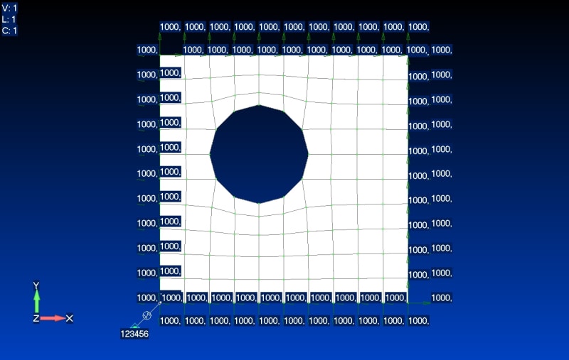
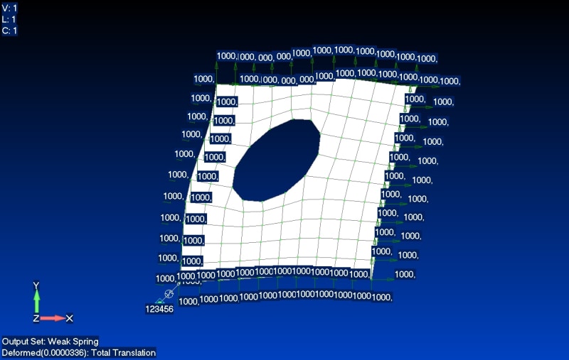
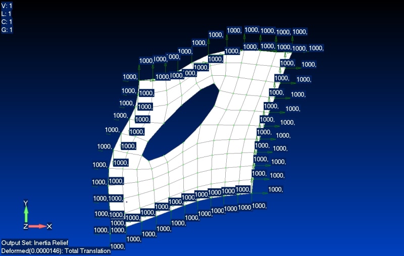
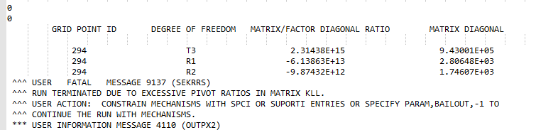
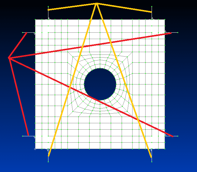
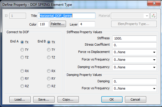
The general approach is OK, but obviously something is off. Instead of using spring elements, try using rod/truss elements. They are similar for this use; just back calculate the k=AE/L (maybe try k=10,000 to 100,000 since k=1,000 may be too small). If that works, then something is incorrect with the spring element inputs. FYI, there are only 3 DOF (1, 2, 3) active for the springs/rods. Beam elements would have 4,5,6 active, but don't use those. The picture associated with the bailout run is not very helpful. Just plot the deformed shape over the original shape (set it to actual scale).

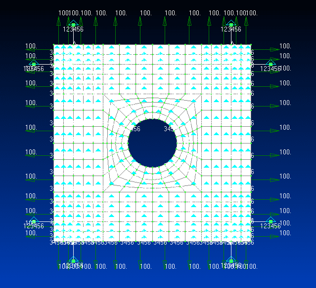
If that still does not work, just use the 3-2-1 approach. For this case, it is just 2-1 (w.r.t corner constraints) since you constrain the plate in the entire z-direction. One corner is constrained in 1,2 and the adjacent corner in just 1 or 2 (depending on the corner). This will be simpler since it seems you are having difficulty with the springs.

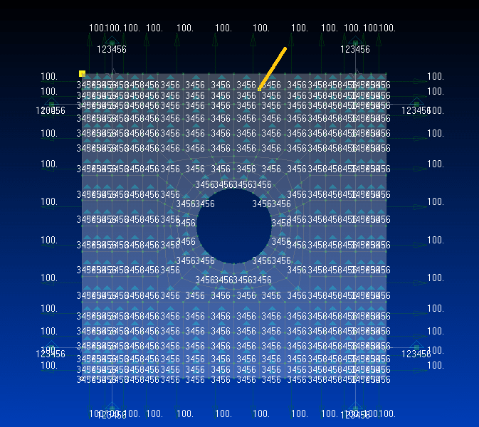
The plate should only be constrained in the 3 direction, not 4,5,6. Constraining the entire plate in 3 automatically stops RBM in 4,5. RBM in 6 is stopped by either the springs/rods or the corner constraints.

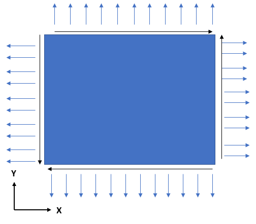
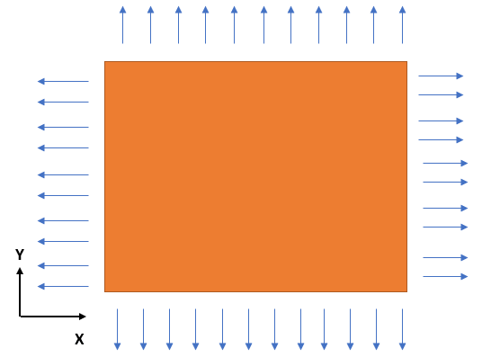
Side note. You should apply an edge load. The pre processor will calculate the correct forces to apply to each node. The nodes at the end will have half the load as the interior load. This is also why the 3-2-1 approach is just fine, but may give some local peak stresses at the constraints. You can not control the actual load at the constrained corners, you just get what you get (as opposed to the actually intended nodal loads).

Last note: As rb1957 stated, you have more springs than necessary. You only need 2 near one corner and 1 at the other (just as if you were constraining the corners for the 3-2-1 or 2-1 in this case). Just make sure they are in the correct directions to stop 1,2,6 for the plate. It won't matter too much if you have 8 and ensure the spring/rod forces are low, but it is better not to introduce overconstraints.
 
Karachun, will try to post the dat file. I believe I have set up the DOF spring element correctly i.e. aligned the spring nodal connection direction with stiffness direction.

RB, I am not familiar with 3-2-1 approach that intimately. Will try to look it up. If you have any material which explains the concept lucidly, I request you to share it with me (or point it out where I can find it). I think the overall concept involves applying minimal BCs to constrain the model while allowing it to deform properly.

ESPComposites, I initially started my analysis by constraining the plate in TZ direction. The RBM error on particular node mentioned RX & RY and thus starting progressively adding 4,5 & 6 constraints to see if it helps. Let me try with reduced number of springs and CBUSH element instead of DOF Spring as suggested by Karachun & see if it resolves the RBM issue.

Folks, thank you for the continued support.
 
"I am not familiar with 3-2-1 approach that intimately. Will try to look it up. If you have any material which explains the concept lucidly, I request you to share it with me (or point it out where I can find it)."

The link about 3-2-1 method already was posted by swimfar, I duplicate it.
 
man, this is such a simple model it "should" run.

1) you are using plate elements, CQUAD4s (in NASTRAN), right ?

2) your loading is in-plane, right ? then there is no action out-of-plane, and freedoms 3,5,6 can be constrained at every node without impacting results.

3) then constraint every node on X edges in y and every node on the Y edges in x. This is not correct modelling but will run (unless there's a major internal problem).

4) once it runs, refine step 3 ... constrain one corner node in x and y and another in x or y (y if on a X edge, x if on a Y edge). This should also run.

5) replace these 3 constraints in 4) with RODs, grounding the far ends. This should run an give good results.

another day in paradise, or is paradise one day closer ?
 
Here is some examples.
Symmetry method is applicable only if you have symmetry model and loads. 3-2-1 method is universal. In your case model can be constrained by one node at corner.
Inertia relief is powerful method for calculating structures with balanced loads, like ships and airplanes; where weight balanced by lift force or Archimedes force.
With option PARAM,INREL,-2 solver find center of gravity of model, make some magic and model will expand about CG or node closest to CG. Stresses will be ok but displacements may look strange, but elongation between two nodes will be the same as with other methods.
With option PARAM,INREL,-1 you select DOF`s in SUPORT card and solver makes magic and scale all translations about desired node/DOF.
Here is some useful links about INREL.
And don’t hesitate to read NX Nastran documentation, you can start with QRG and search INREL option. There is a whole chapter in User Guide, chapter 18.
And you can use "Perfectionist method" and model only 1/8 of structure.
And all these methods are applicable only to balanced structures, sum of forces is near zero. Otherwise, you have to model real constraints.
 
Status
Not open for further replies.

Part and Inventory Search

Sponsor